
Capacitive soil moisture sensor

a moisture sensor and capacitive technology, applied in watering devices, resistance/reactance/impedence, instruments, etc., can solve the problems of limited useful life, difficult installation and maintenance of sensors, and abundance of water, and achieve the effect of stable long-term us

Inactive Publication Date: 2006-12-28
LEE FU CHING
View PDF13 Cites 20 Cited by
  • Summary
  • Abstract
  • Description
  • Claims
  • Application Information

AI Technical Summary

Benefits of technology

[0018] (g) provides s

Problems solved by technology

Some plant matter suffers in an abundance of water and others in a lack of.
These types of sensors were therefore difficult to install and maintain.
These types of sensors provided immunity to the composition of the soil but suffer from a limited useful life since the dielectric material degrades with time.
Additionally these sensors suffer from slow response since the dielectric material takes time to reach the same moisture level as the surrounding soil.
These sensors provide immunity to the composition of the soil, however, with these sensors it is difficult to determine the wetness at a particular depth.
This causes the density of the soil to change and therefore the measured wetness is not a true representation of the original soil sample.
Other available sensors are generally not suitable for the layman and or require expensive measuring equipment.

Method used


Image

  • Capacitive soil moisture sensor
  • Capacitive soil moisture sensor
  • Capacitive soil moisture sensor

Examples


Embodiment Construction

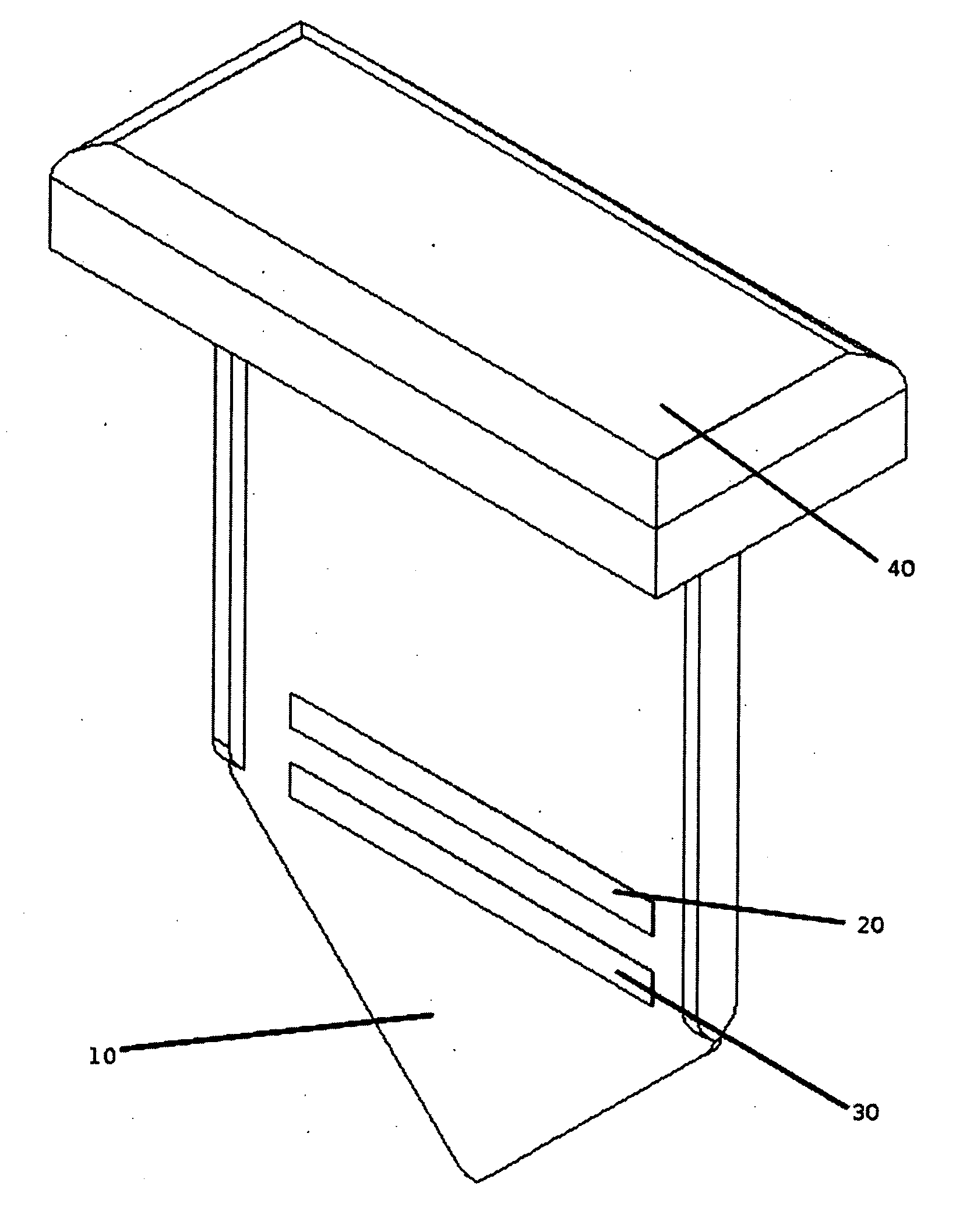
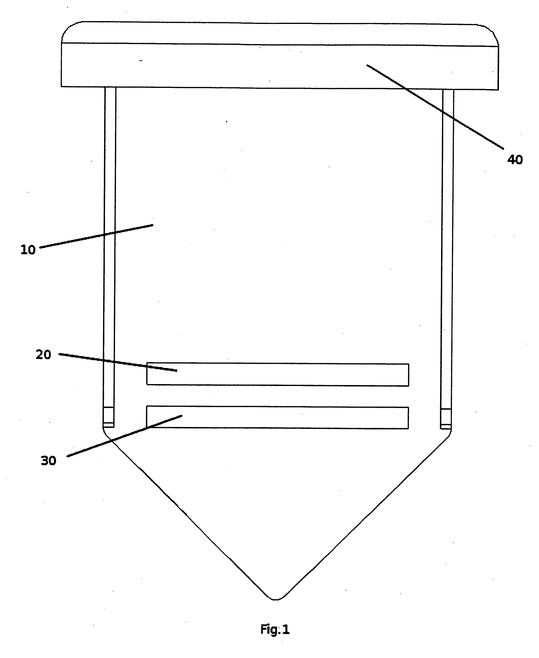
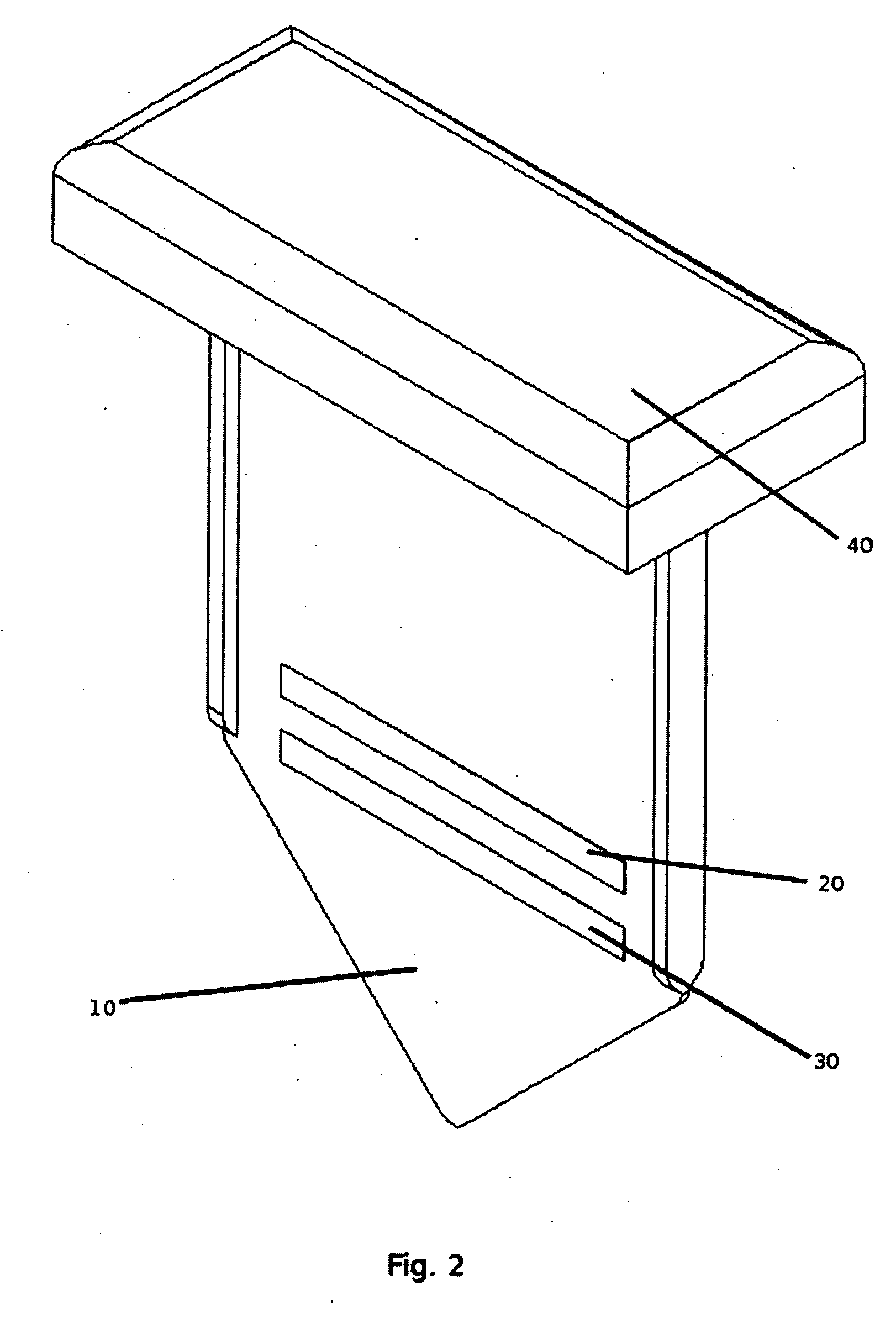
[0025] The preferred embodiment of the present invention, as shown in FIG. 1 and FIG. 2, comprises of a body 10 which is made of a corrosion resistant and ultra-violet light resistant material such as fiber glass, polyurethane, ABS or similar. Body 10 is formed into a flat and thin sheet to allow easy insertion into the soil. Additional rib structures to act as stiffeners can be form as part of body 10 to prevent twisting and bending during the insertion process.

[0026] A plurality of conductive material is attached to body 10 to form a first electrode 20. A plurality of conductive material is similarly attached to body 10 to form a second electrode 30. The conductive material of first electrode 20 and second electrode 30 are preferably corrosive resistant metals such as gold or platinum, however due to the cost of such metals, other materials such as copper, bronze, zinc, nickel or similar can be used. Additionally conductive resins can be used in place of the metals.

[0027]FIG. 4 ...


PUM


Abstract

A capacitive soil moisture sensor that is easy to install, does not require complex calibration, can sense moisture at a particular depth, can accommodate soils of different composition, does not alter soil densities, provides fast response to changes in moisture and provides stable long term use. The sensor comprising of a body (10) onto which is attached a plurality of first electrode (20) and a plurality of second electrode (30). A plurality of protective layer (50) of low dielectric constant material is applied over the electrodes and against the body (10) to provide a physical barrier to prevent a conduction path from the first electrode (20) to the second electrode (30) and to provide protection against physical damage. The first and second electrodes (20), (30), once inserted into the soil, forms a capacitor with the soil as the dielectric. A change in soil moisture causes the capacitance of the sensor to change.

Description

CROSS-REFERENCE TO RELATED APPLICATION [0001] Not Applicable FEDERALLY SPONSORED RESEARCH [0002] Not Applicable SEQUENCE LISTING OR PROGRAM [0003] Not Applicable FIELD OF INVENTION [0004] The present invention relates to a soil moisture sensor and more particularly, to a soil moisture sensor that measures the moisture of an area of soil at a particular depth. BACKGROUND OF INVENTION [0005] In the field of irrigation it is necessary to ensure that water is properly controlled and supplied to vegetation. Some plant matter suffers in an abundance of water and others in a lack of. To this end, it is important to be able to determine the water content of the supporting soil particularly in the regions proximate to the vegetation's major root structures. [0006] Many examples of sensors are detailed in prior art and can be loosely group into the following: [0007] Resistive / conductive sensors. U.S. Pat. No. 4,796,654 is an example. These type of sensors rely on the resistive / conductive prop...

Claims


Application Information

Patent Timeline
IPC IPC(8): G01R27/26
CPCA01G25/167G01N33/246G01N27/223
Inventor LEE, FU CHING
Owner LEE FU CHING
Learn More