Artificail vision system

a vision system and artificial vision technology, applied in the field of artificial vision systems, can solve the problems of reduced or deadened photoreceptor cells, visual defects, advanced blindness, etc., and achieve the effect of increasing the power supply capacity and stable long-term us

Active Publication Date: 2006-03-16
NIDEK CO LTD +1
View PDF18 Cites 48 Cited by
  • Summary
  • Abstract
  • Description
  • Claims
  • Application Information

AI Technical Summary

Benefits of technology

[0014] The artificial vision system is constructed of the separately provided external device and internal device as above. Accordingly, the external device can be provided with many functions and an increased capacity of the power supply, which allows stable long-term use.

Problems solved by technology

Retinitis pigmentosa, age-related macular degeneration, and others cause visual defects and may lead to blindness at an advanced stage.
When the retinitis pigmentosa, age-related macular degeneration, and others occur, the photoreceptor cells are reduced or deadened and thus could not convert the light signal to the electrical signal.
Consequently, a person would lose his vision.
H11(1999)-506662, however, the microphotodiode is generally located on only a part of the retina, resulting in a problem that a visual field is extremely narrow (about 10° of a visual angle).
The patient therefore could not easily distinguish the surrounding circumstances and particularly would find it difficult to visually recognize a moving object.
However, the implanting operation onto a spherical retina would be hard.
This would cause a problem that portions surrounding the electrode setting site are also peeled, which leads to retinal detachment after the operation.
On the other hand, the optic papilla stimulating type implant for electrically stimulating the optic nerve from the surrounding portions has a disadvantage that the number of electrodes could not be increased and therefore effective vision could not be provided.
The brain cortex stimulating type implant has also a problem that an information processing system is complicated and it is hard to give stimulation close to an ordinary view.

Method used


Image

  • Artificail vision system
  • Artificail vision system
  • Artificail vision system

Examples


Embodiment Construction

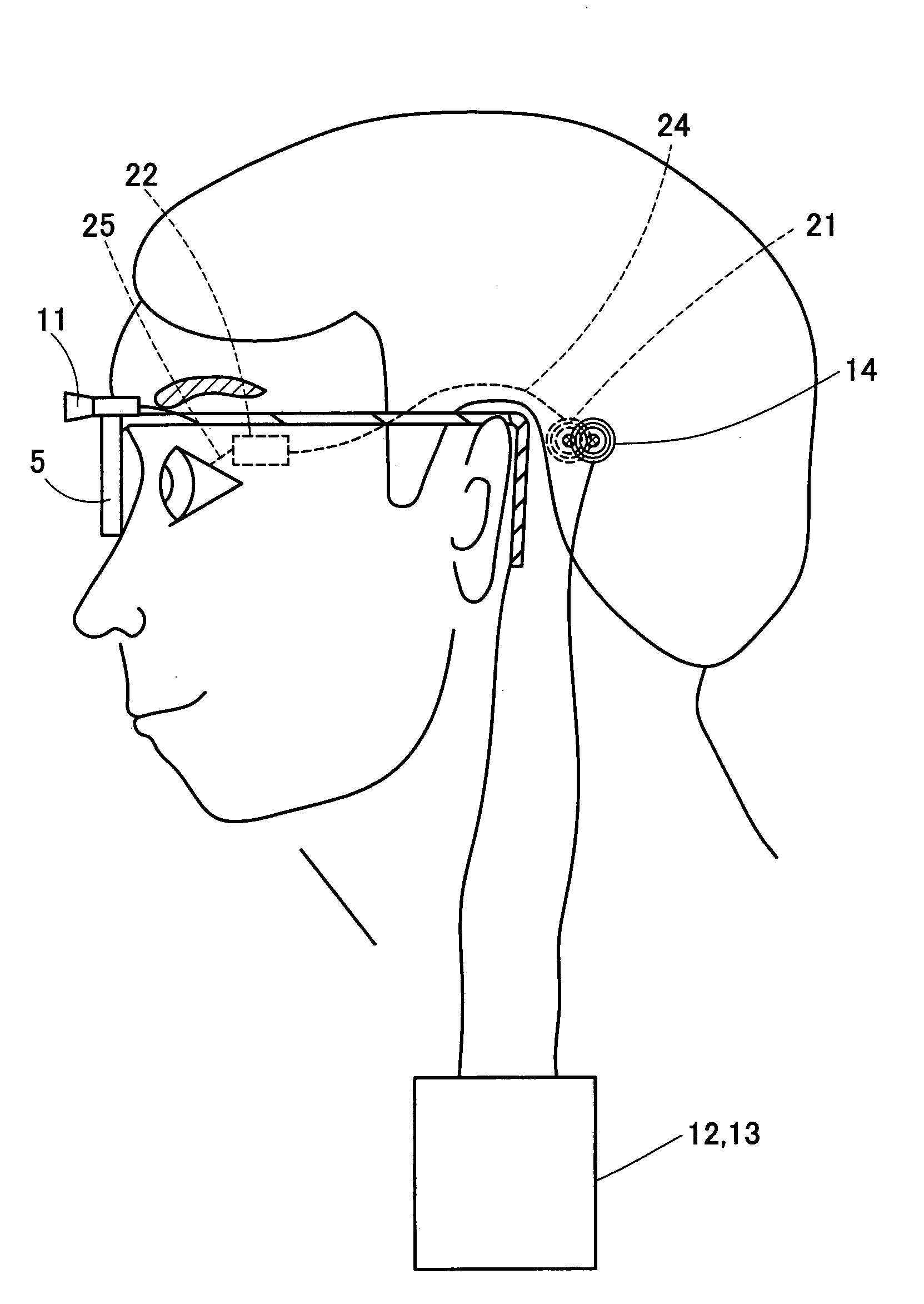
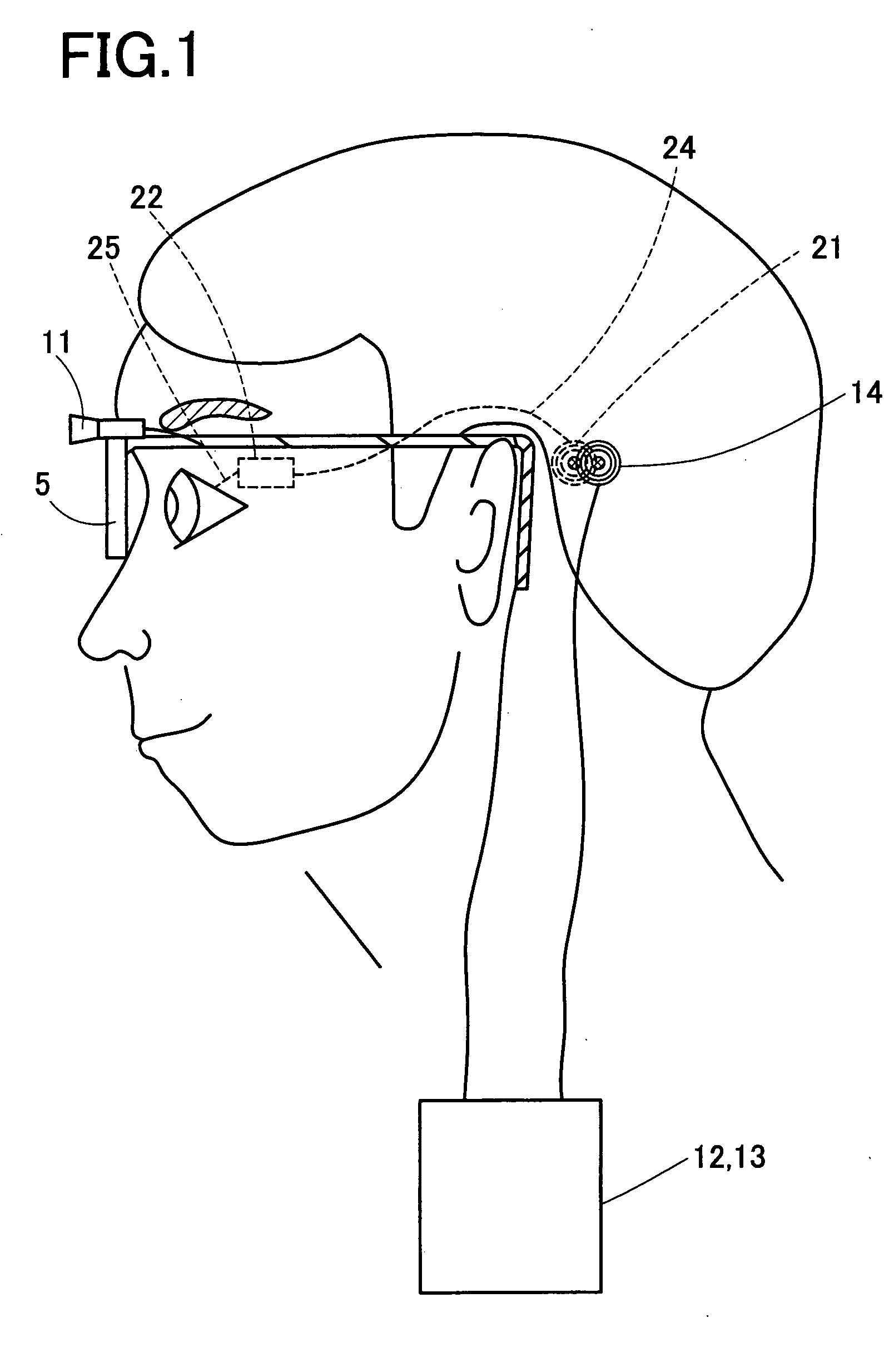
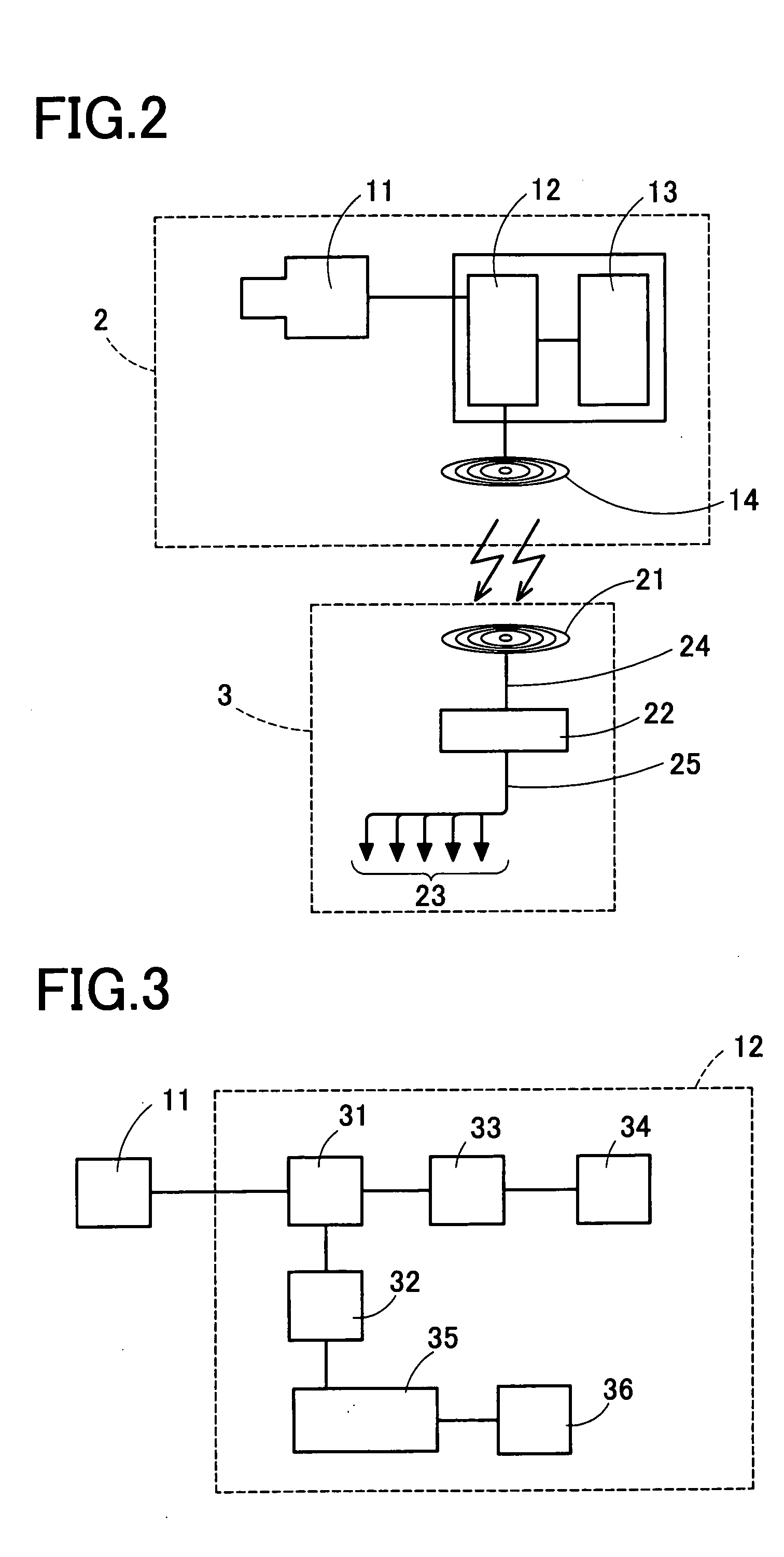
[0022] A detailed description of a preferred embodiment of an artificial vision system embodying the present invention will now be given referring to the accompanying drawings. FIG. 1 is a view showing an in-use state of the artificial vision system in the present embodiment. FIG. 2 is a block diagram showing a schematic structure of the artificial vision system.

[0023] The artificial vision system 1 in the present embodiment is constructed of an external device 2 which a patient wears in use and an internal device 3 which is surgically implanted in advance in the patient himself. The external device 2 is arranged such that a camera 11 is mounted on a visor 5 which the patient puts on like glasses to capture a video image of an object space in front of the patient who turns his face. For example, a CCD camera with an image pickup device of tens of thousands of pixels is used as the camera.

[0024] The camera 11 is connected to an image processing device 12 which conducts predetermine...


PUM


Abstract

An object is to provide an artificial vision system ensuring a wide field of view without damaging a retina. In the artificial vision system, a plurality of electrodes (23) are to be implanted so as to stick in an optic papilla of an eye of a patient. A signal for stimulation pulse is generated based on an image captured by an image pick up device (11) to be disposed outside a body of the patient. The electrical stimulation signals outputted from the electrodes (23) based on the signals for stimulation pulse stimulate an optic nerve of the eye, thereby enabling the patient to visually recognize the image from the image pickup device (11).

Description

TECHNICAL FIELD [0001] The present invention relates to an artificial vision system for artificially giving a visual signal, and more particularly to an artificial vision system of an optic papilla stimulating type for applying an electrical signal to an optic papilla in which nerve fibers running throughout a retina join, thereby inducing restoration of vision. BACKGROUND ART [0002] Retinitis pigmentosa, age-related macular degeneration, and others cause visual defects and may lead to blindness at an advanced stage. Human eyes normally work such that, when light is irradiated to a retina, a light signal is converted to an electrical signal through photoreceptor cells, and this electrical signal is turned into a pulse signal through retinal ganglion cells and is transmitted to a brain. When the retinitis pigmentosa, age-related macular degeneration, and others occur, the photoreceptor cells are reduced or deadened and thus could not convert the light signal to the electrical signal....

Claims


Application Information

Patent Timeline
Patent Type & Authority Applications(United States)
IPC IPC(8): A61N1/18A61F9/007A61F2/14A61F9/08A61N1/36
CPCA61F9/08A61N1/0543A61N1/3727A61N1/37229A61N1/36046
Inventor TANO, YASUOFUJIKADO, TAKASHIFUKUDA, YUTAKAYAGI, TETSUYA
Owner NIDEK CO LTD
Why Eureka
Try Eureka