Traction power supply network tail end voltage boosting device with power fusing function and method of device

A traction power supply and power integration technology, applied in circuit devices, harmonic reduction devices, AC network voltage adjustment, etc., can solve the problems of low power factor, small series compensation capacity, and single function on the measurement and assessment side of the substation, and achieve Improve the overall capacity utilization, suppress the vehicle network resonance function, and suppress the effects of ripple current

Active Publication Date: 2015-09-09
ZHUZHOU NAT ENG RES CENT OF CONVERTERS
View PDF7 Cites 15 Cited by
  • Summary
  • Abstract
  • Description
  • Claims
  • Application Information

AI Technical Summary

Problems solved by technology

[0003] 1) Adopt the method of adding substations, such as the Yanqing traction network of Daqin Line; but this type of method requires large investment and high cost;
[0004] 2) The method of using series capacitor compensation device to increase the network voltage at the end of the traction network, such as Bao (Chicken)-Lan (Zhou) Second Line Tong (Anyi) Tang (Jiabao) traction network; Its actual improvement effect is not good;
[0005] 3) Adopt the method of adjusting the transformer tap to increase the transformer outlet voltage. Due to the operating characteristics of the locomotive itself and the limitations of the compensation device, this type of method has a very limited effect on improving the network voltage at the end of the power supply arm;
[0007] From the above, it can be seen that the installation of FC devices or TSC devices at the end of the traction power supply can only achieve a single network voltage boosting function, and it has great limitations to increase the voltage solely by relying on the capacitive reactive power provided by FC or TSC. Reversing capacitive reactive power to the traction power supply system will lead to long-term low power factor on the measurement and assessment side of the substation, and serious fines. At the same time, due to frequent fluctuations in the network voltage of the traction power supply system; and if FC devices are used, it cannot With dynamic adjustment of capacitive reactive power, the network voltage of the traction system will also fluctuate frequently, which is not conducive to safe driving; if the TSC device is used, it will cause frequent switching of the device, which is not conducive to the safe and stable operation of the equipment
[0008] To sum up, the network voltage boosting method at the end of the traction power supply in the existing technology, on the one hand, has limited lifting effect and high cost, and cannot achieve high-performance network voltage boosting function; on the other hand, because it can only be used as a single network The voltage lifting device cannot be combined with power quality management to solve the power quality problem at the power supply end of the traction network. The function is single, the cost performance is not high, and there are safety performance problems of the power grid

Method used


Image

  • Traction power supply network tail end voltage boosting device with power fusing function and method of device
  • Traction power supply network tail end voltage boosting device with power fusing function and method of device
  • Traction power supply network tail end voltage boosting device with power fusing function and method of device

Examples


Embodiment Construction

[0039] The present invention will be further described below in conjunction with the accompanying drawings and specific preferred embodiments, but the protection scope of the present invention is not limited thereby.

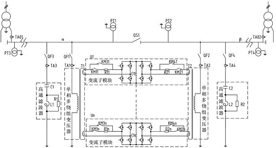
[0040] Such as figure 1 As shown, this embodiment has a traction power supply terminal network voltage lifting device with power integration function, including:

[0041] The multiple step-down module is used to connect to the power supply of the two power supply arms at the end of the traction network and step down the voltage. It includes two single-phase multi-winding transformers with the same structure. The two single-phase multi-winding transformers are respectively connected to two Power supply arm power supply, corresponding to multiple sets of α-arm voltage and β-arm voltage after output voltage reduction;

[0042] The power integration and conversion module is used to convert the energy of the connected two power supply arm power sources respectively,...


PUM


Abstract

The invention relates to a traction power supply network tail end voltage boosting device with a power fusing function and a method of the device. The device includes a multiple voltage reduction module and a power-fusing current-converting module; the multiple voltage reduction module is connected into two power supply arm power sources of the tail end of a traction power supply network and includes two single-phase multi-winding transformers of the same structure which are correspondingly connected into the two power supply arm power sources respectively through connection switches; the power-fusing current-converting module is used for performing energy conversion on the two power supply arm power sources and includes a plurality of current conversion sub modules; one set of voltage is connected into two input sides of each current conversion sub module through corresponding secondary windings of the two single-phase multi-winding transformers, so that energy conversion can be performed; and through controlling the switch-on of the current conversion sub modules, output voltage can be boosted, and power fusion of the two power supply arms can be performed. According to the method of the invention, the voltage of the tail end of the traction power supply network can be stabilized and boosted through controlling the power-fusing current-converting module. The device and the method of the invention have the advantages of simple structure, low cost, power fusion and train power network resonance suppression, and can boost the voltage of the tail end of the traction power supply network.

Description

technical field [0001] The invention relates to the technical field of network voltage energy management at the end of a traction network, in particular to a network voltage raising device at the end of a traction power supply with a power integration function and a method thereof. Background technique [0002] In recent years, with the increasing traffic density and single-car power of my country's electrified railways, the voltage of the long power supply arm of the traction network has dropped seriously, which has affected the normal operation of electric locomotives and limited the further increase of transportation capacity. For the low network voltage problem at the end of the traction power supply, there are currently the following solutions: [0003] 1) Adopt the method of adding substations, such as the Yanqing traction network of Daqin Line; but this type of method requires large investment and high cost; [0004] 2) The method of using series capacitor compensati...

Claims


Application Information

Patent Timeline
Patent Type & Authority Applications(China)
IPC IPC(8): H02J3/00H02J3/16H02J3/18H02J3/01B60M3/02
CPCY02E40/30Y02E40/40
Inventor 吕顺凯邱文俊周方圆吴强罗仁俊黄燕艳张定华王才孝龙礼兰胡前毛金平朱建波文韬吴明水龚芬涂绍平周靖潘燕
Owner ZHUZHOU NAT ENG RES CENT OF CONVERTERS
Why Eureka
Try Eureka