Apparatus and method for providing live dinoflagellates for toxicity tests

a technology of dinoflagellates and toxicity tests, which is applied in the field of apparatus and methods for providing live dinoflagellates for toxicity tests, can solve the problems of time-consuming and costly on-site procedures

Inactive Publication Date: 2010-11-23
THE GOVERNMENT OF THE UNITED STATES OF AMERICA AS REPRESENTED BY THE SEC OF THE NAVY NAVAL RES LAB WASHINGTON
View PDF1 Cites 3 Cited by
  • Summary
  • Abstract
  • Description
  • Claims
  • Application Information

AI Technical Summary

Problems solved by technology

Current apparatuses and methods of providing live dinoflagellates for use in water, soil, and sediment toxicity tests typically involve time-consuming and costly on-site procedures such as maintaining stock cultures of dinoflagellates in incubators, dividing the cultures, adding new media to the cultures, and counting dinoflagellate cells with a microscope for test setup.

Method used


Image

  • Apparatus and method for providing live dinoflagellates for toxicity tests
  • Apparatus and method for providing live dinoflagellates for toxicity tests
  • Apparatus and method for providing live dinoflagellates for toxicity tests

Examples


Embodiment Construction

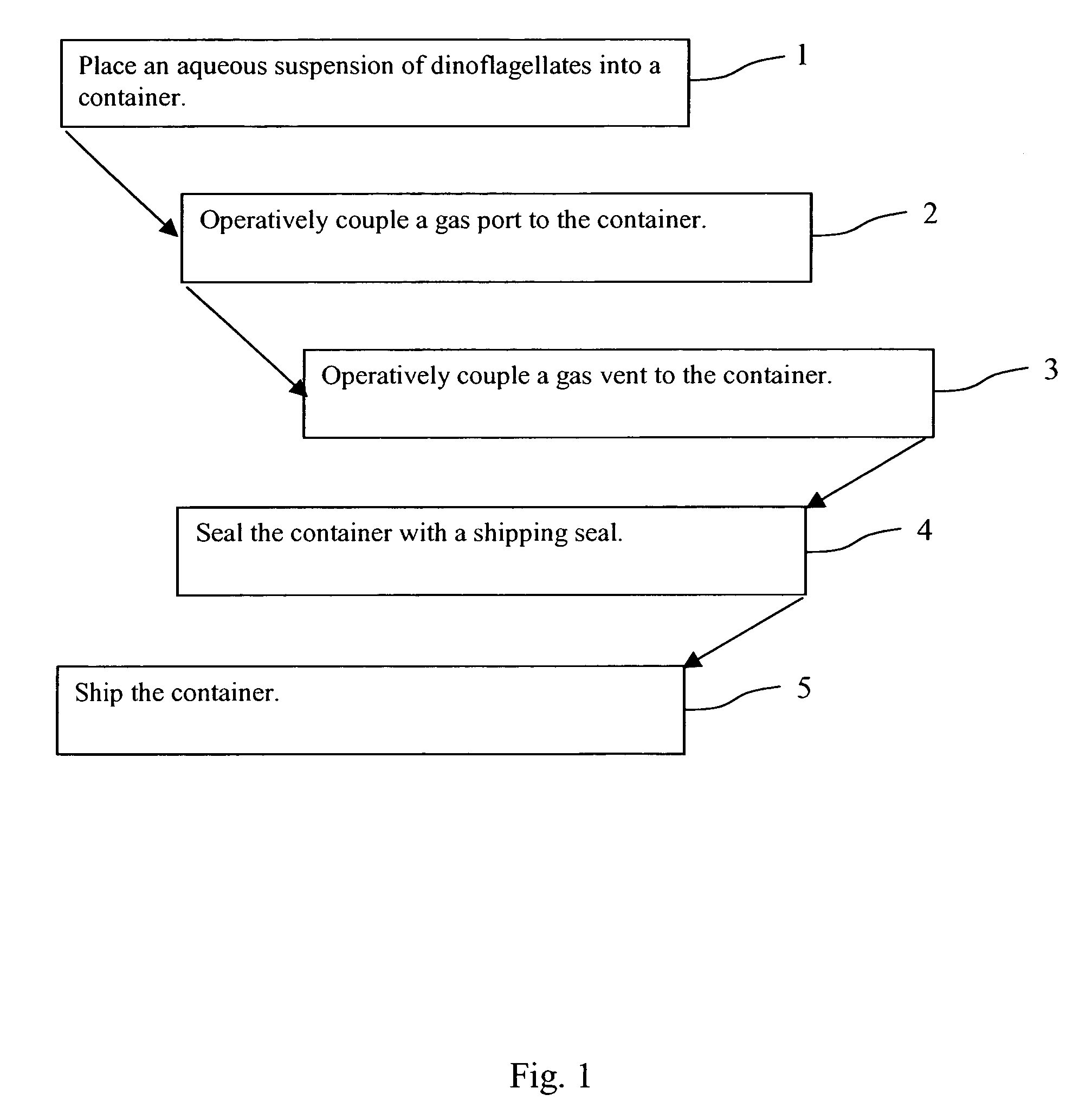
[0020]FIG. 1 is a flowchart of a method for using a cartridge 220, as shown in FIG. 2, to provide live, test-quality dinoflagellates 10 for substance toxicity tests. The cartridge 220 is a component of a toxicity test system 200, as shown in FIG. 3, that measures the fluorescence and bioluminescence capabilities of the dinoflagellates 10. The cartridge 220 comprises a container 300, a gas port 250, a gas vent 350, and an aqueous suspension 30. In step one, the aqueous suspension 30 that comprises dinoflagellates 10 may be placed into the container 300. In step two, the gas port 250 may be operatively coupled to the container 300. In step three, the gas vent 350 may be operatively coupled to the container 300. In step four, the container 300 may be sealed with a shipping seal 330, described below, to prevent the aqueous suspension 30 from exiting the container 300. Finally, in step five, the cartridge 220 may be shipped.

[0021]FIG. 3 illustrates the interoperability of the cartridge 2...


PUM

PropertyMeasurementUnit
wavelengthaaaaaaaaaa
bioluminescenceaaaaaaaaaa

Abstract

A cartridge comprising: a container having a lower end; an aqueous suspension of dinoflagellates contained in the container; a gas port operatively coupled to the container, the port capable of directing a gas into the aqueous suspension in the lower end of the container; a gas vent operatively coupled to the container; and a shipping seal operatively coupled to the container to prevent the aqueous suspension from exiting the container.

Description

CROSS-REFERENCE TO RELATED APPLICATIONS[0001]This application is a continuation in part of both U.S. application Ser. No. 11 / 586,747, filed Oct. 10, 2006, now abandoned entitled “Method for Stimulation of Bioluminescent Organisms Via Turbulence Created by Gas Bubbles” (Parent Application 1) (Navy Case # 98122); and U.S. application Ser. No. 11 / 586,745, filed Oct. 10, 2006, now U.S. Pat. No. 7,704,731 entitled “System and Method for Quantifying Toxicity in Water, Soil, and Sediments” (Parent Application 2) (Navy Case # 98125). Both Parent Application 1 and Parent Application 2 are hereby incorporated by reference herein in their entirety for their teachings.FEDERALLY-SPONSORED RESEARCH AND DEVELOPMENT[0002]This invention was developed with federal funds and is assigned to the United States Government. Licensing and technical inquiries may be directed to the Office of Patent Counsel, Space and Naval Warfare Systems Center, San Diego, Code 20012, San Diego, Calif., 92152; telephone (61...

Claims


Application Information

Patent Timeline
Patent Type & Authority Patents(United States)
IPC IPC(8): C12N1/10C12Q1/00C12N1/04C12M1/34C12N1/00
CPCC12Q1/24G01N33/1866G01N33/5097
Inventor BJORNDAL, BRYANLAPOTA, DAVID
Owner THE GOVERNMENT OF THE UNITED STATES OF AMERICA AS REPRESENTED BY THE SEC OF THE NAVY NAVAL RES LAB WASHINGTON
Why Eureka
Try Eureka