Low clearance centralizer and method of making centralizer

a technology of low clearance and centralizer, which is applied in the direction of manufacturing tools, sealing/packing, and well accessories, etc., can solve the problems of limiting the restrictions through which the centralizer can be manufactured, increasing the minimum collapsed diameter of the casing centralizer, and reducing the efficiency of manufacturing the centralizer

Active Publication Date: 2010-12-07
INNOVEX DOWNHOLE SOLUTIONS INC
View PDF36 Cites 30 Cited by
  • Summary
  • Abstract
  • Description
  • Claims
  • Application Information

AI Technical Summary

Problems solved by technology

This overlapping structure adds to the radial thickness of a centralizer of comparable strength, thereby increasing the minimum collapsed diameter of the casing centralizer and limiting the borehole restrictions through which the centralizer and a casing can pass.
The cost of manufacturing the centralizer is also an important consideration.
While the end result is useful, the costs of manufacturing multiple components, and the costs associated with assembling the components into a centralizer, make these devices relatively expensive.

Method used


Image

  • Low clearance centralizer and method of making centralizer
  • Low clearance centralizer and method of making centralizer
  • Low clearance centralizer and method of making centralizer

Examples


Embodiment Construction

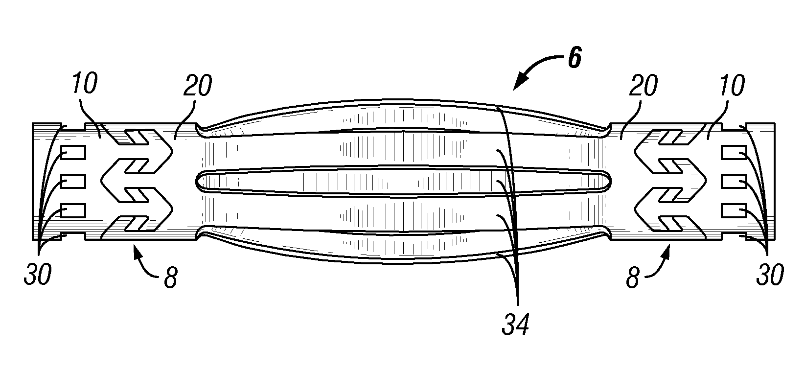
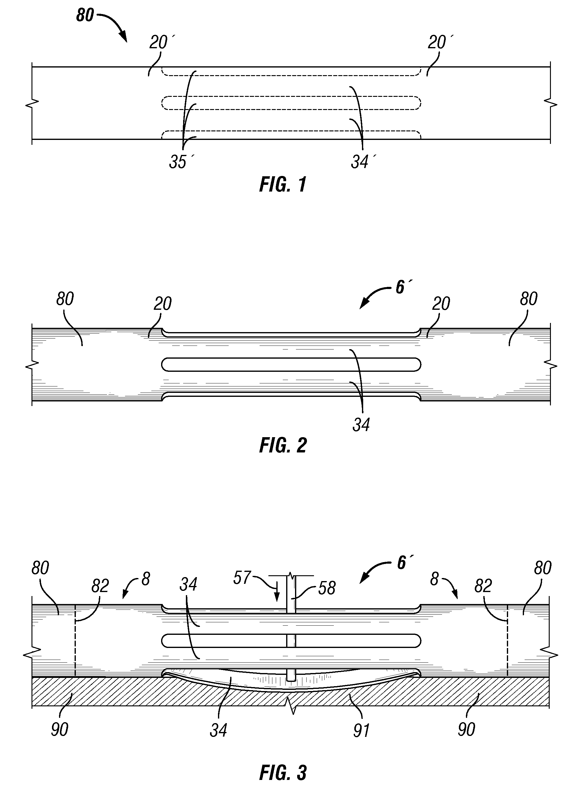
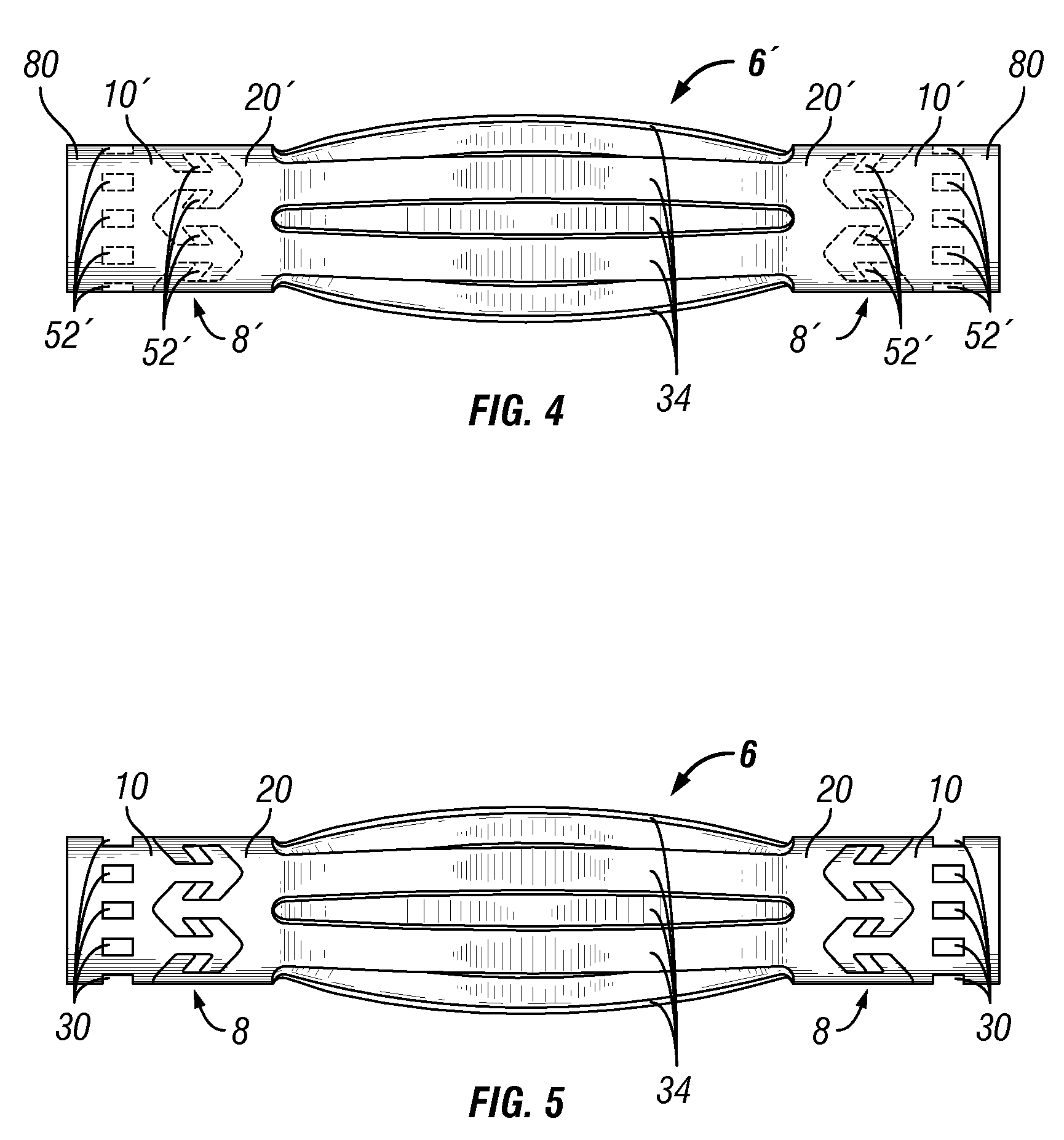
[0028]The present invention provides a centralizer and a method of forming a centralizer. The centralizer of the present invention comprises three members: a cage comprising a plurality of bow springs intermediate a first extendable collar and a second extendable collar. The centralizer of the present invention is cut from a tube using a laser or some other device for precision cutting the wall of a tube.

[0029]In one embodiment of the method of the present invention, the tube is cut, preferably using a laser, along a pre-programmed pattern to remove generally elongate material coupons to form an open-ended and generally tubular cage having a plurality of generally parallel ribs. The ribs are preferably equi-angularly distributed about the axis of the tube. At each end of the cage, and after the ribs of the cage are formed into bow springs, the remaining portions of the tube are cut to form a pair of opposed extendable collars, each comprising a stop collar and a moving collar. The s...


PUM

PropertyMeasurementUnit
shapeaaaaaaaaaa
circumferential widthaaaaaaaaaa
flexibleaaaaaaaaaa

Abstract

A bow-spring centralizer includes a center assembly having a plurality of bow springs and a pair of generally tubular moving collars secured one to each end of each bow spring, the center assembly formed intermediate a pair of generally tubular stop collars. Each moving collar / stop collar combination forms an interlocking and axially extendable collar. The centralizer is formed from a single tube. The tube is cut using a laser according to a cut pattern that creates interlocked stop collar / moving collar combinations that are rotatably locked but axially movable one relative to the other. Each of the interlocked stop collars and moving collars includes a plurality of circumferentially spaced heads, each head integrally formed on one of a plurality of circumferentially spaced extensions protruding from the stop collar or moving collar. The heads may have a variety of projected shapes, such as a rectangular, arrow or a teardrop shaped. Each head is axially slidably captured within one of a plurality of chambers on the other tubular member (stop collar or moving collar) to which the first member is coupled. The extensions of each interlocked tubular member define the outer walls of the chamber in which a head of the opposing tubular member is slidably captured.

Description

BACKGROUND OF THE INVENTION[0001]1. Field of the Invention[0002]This invention is directed to casing centralizers having flexible bow springs for use in borehole completion operations, and particularly to centralizers that may be radially collapsed to pass through a small annular space, and that can deploy to generally center a casing within a borehole. More specifically, the present invention is directed to an integrally-formed centralizer in which the collars and the bow springs may be formed from a single tube.[0003]2. Description of the Related Art[0004]Centralizers are commonly secured at spaced intervals along a casing or tubing string to provide radial stand-off of the casing or tubing from the interior wall of a borehole in which the string is subsequently installed. The centralizers generally comprise generally aligned collars defining a bore there through for receiving the casing, and a plurality of angularly-spaced ribs that project radially outwardly from the casing stri...

Claims


Application Information

Patent Timeline
Patent Type & Authority Patents(United States)
IPC IPC(8): B23P13/04B21D28/00E21B17/10
CPCE21B17/1028Y10T29/49863Y10T29/49906Y10T29/49609Y10T29/49995
Inventor BUYTAERT, JEANMILLER, EUGENE EDWARDYOUNG, JIMMY MACK
Owner INNOVEX DOWNHOLE SOLUTIONS INC
Why Eureka
Try Eureka