
Cord organizer

a technology for organizing and cords, applied in the field of organizers, can solve the problems of providing almost no way to organize such cords in vehicles, providing no means to organize a plurality of such cords, and the average consumer fails to appreciate the rather large investment he has in electrical, acoustic or cable cords or welding cables and water hoses

Inactive Publication Date: 2010-12-14
WILKINSON CHARLES ERVIN
View PDF36 Cites 18 Cited by
  • Summary
  • Abstract
  • Description
  • Claims
  • Application Information

AI Technical Summary

Benefits of technology

"The present invention is an organizer device with a primary back strap and a removable cinch strap. The device allows for the attachment of multiple coiled cords, power tool boxes, or other materials to a suspended storage. The primary back strap has two attachment locations with corresponding removable cinch straps, which can be easily removed without needing to remove the suspended primary back strap. The removable auxiliary belt has a main strap with a plurality of loop straps permanently affixed to it, allowing for the attachment of multiple coiled cords or power tool boxes. The technical effects of the invention include efficient storage and easy attachment of multiple cords and tools."

Problems solved by technology

While these patented straps were a good improvement over ties, string and hooks mounted on walls to store a coil of cord, they provided no means to organize a plurality of such cords except by providing multiple hooks in the walls.
Secondarily the devices provided almost no way to organize such cords in a vehicle.
Often the cords get intertwined and tangled together creating a mess.
The average consumer fails to appreciate the rather large investment he has in electrical, acoustic or cable cords or welding cable and water hoses.
However, improper storage and damage to those components costs a lot of money.
For the professional craftsman both the damage issue and the lost time in untangling multiple lines results in substantial cost.

Method used


Image

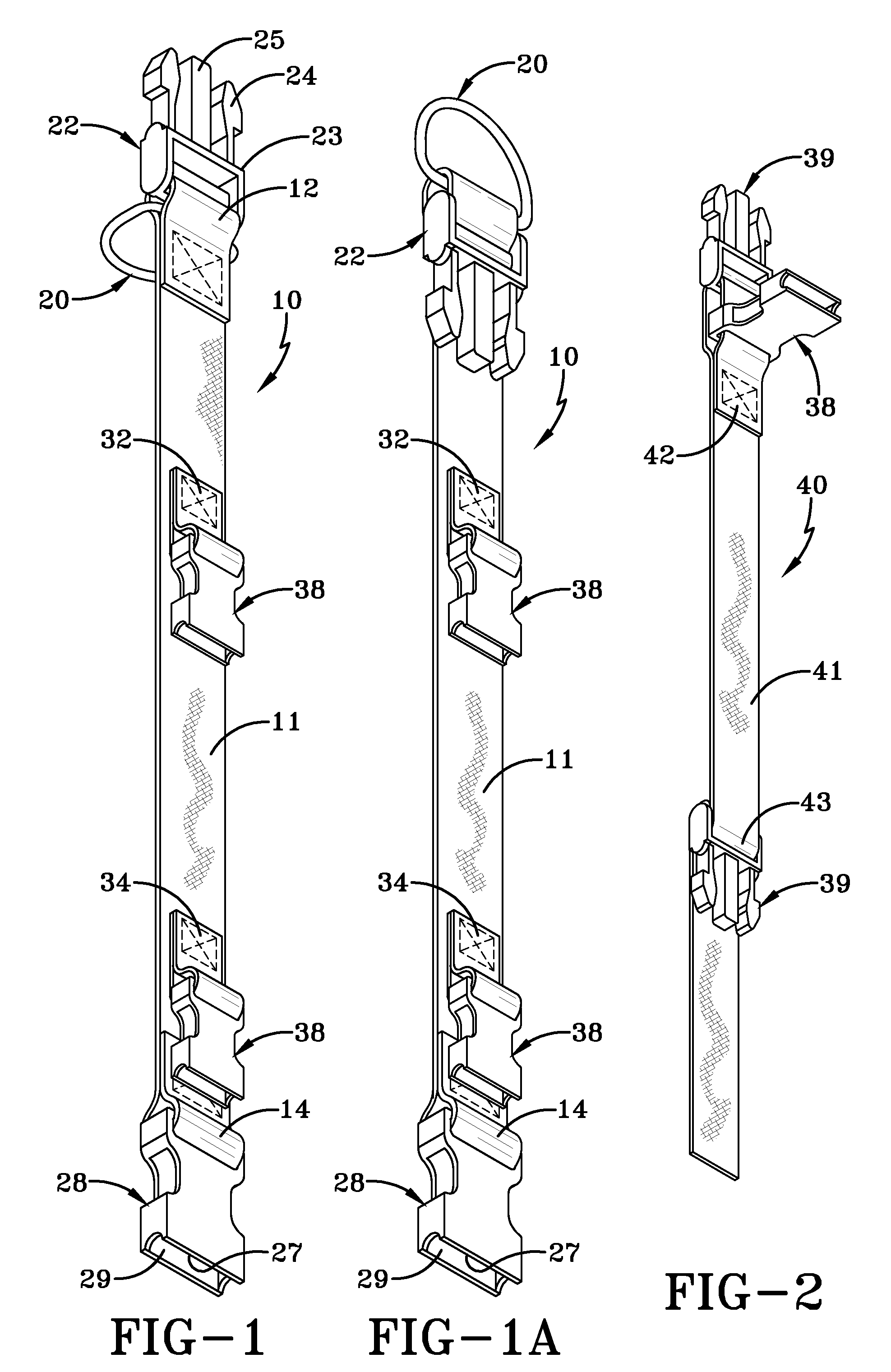
  • Cord organizer
  • Cord organizer
  • Cord organizer

Examples


Embodiment Construction

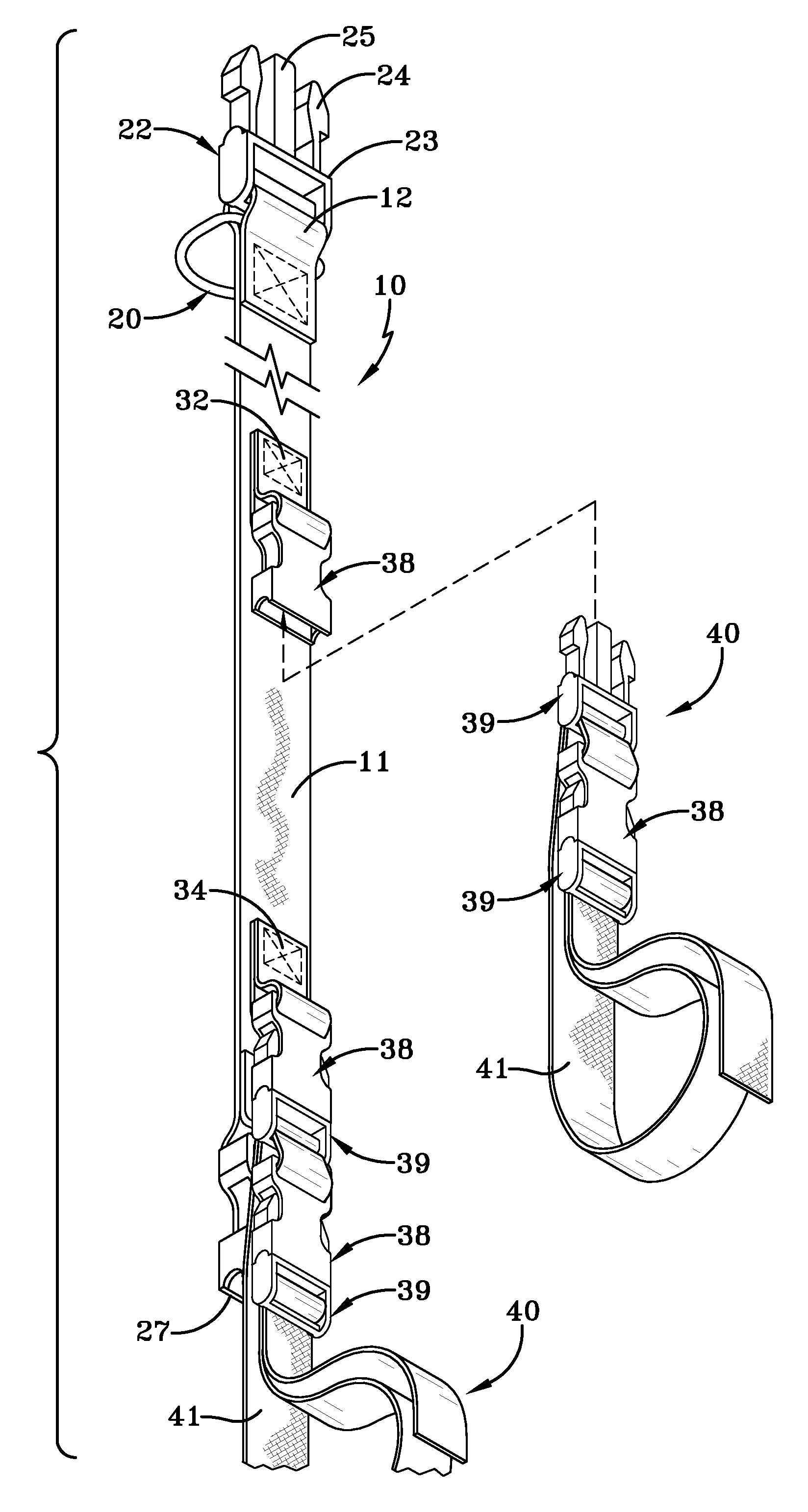
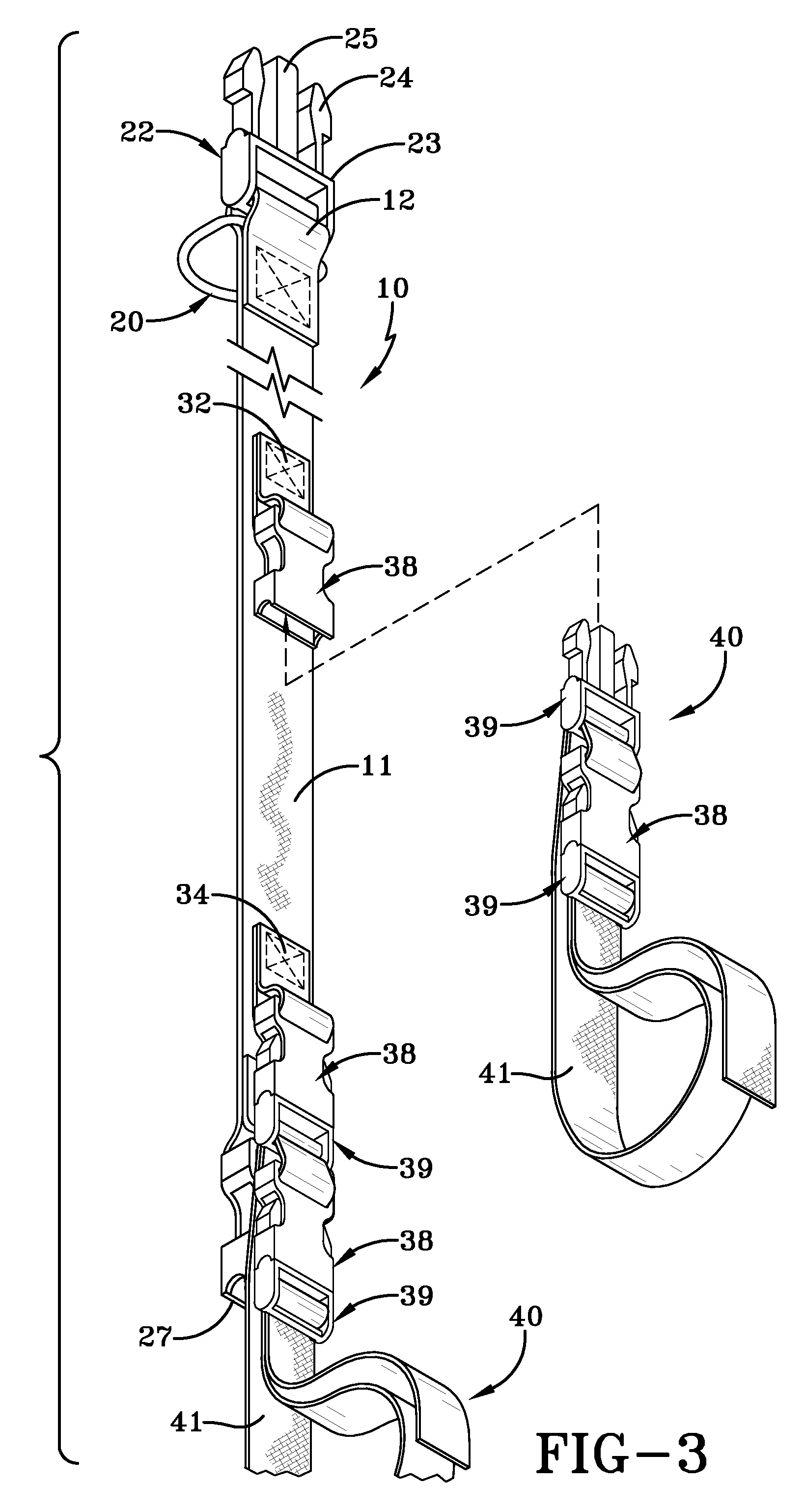
[0027]The present invention in its preferred embodiment has a primary back strap 10 and one or more removable cinch straps 40 for holding a coil of cord or cable 100 or any other material such as a power tool box.

[0028]With reference to FIGS. 1 and 1A the primary back strap 10 is shown in a fully extended condition having a first looped end 12 with a metal D ring 20 and a first buckle portion 22 attached. The first buckle portion 22 has a pair of laterally opposed flexible clasps 24 and a center rod 25 all adapted to enter a second buckle portion 28 and make a spring locking engagement. The first buckle portion 22 hereinafter will be referred to as the male buckle portion 22 while the second portion 28 with a hollow internal receiving cavity 29 will be referred to as the female buckle portion 28 as is understood in the art. As shown at the opposite looped end 14 of the primary back strap 10 is attached a female buckle portion 28. As shown the looped ends 12, 14 are stitched to the s...


PUM


Abstract

The present invention is an organizer device having a primary back strap 10, the primary back strap 10 having a first end, a second end and a middle portion. The first end having a first buckle portion 32 and a means for suspending the back strap 20, the second end having a second buckle portion 28, the middle portion having at least one attachment location with an appended buckle portion 38 interposed between the first and second ends; and wherein the second end is provided to receive the first end of a second primary back strap. The device further has at least one removable cinch strap device 40 having a first end and a second end, the first end having two buckle portions 38, 39, a first buckle portion 39 for removable attachment to the attachment location with an appended buckle 38 on the primary back strap 10 and a second buckle portion 39 to attach to the buckle portion at the second end of the cinch strap 40 to form a loop for holding a coil of cable 100, a power tool box or other material.

Description

FIELD OF THE INVENTION[0001]This invention relates to devices for holding and storing coiled lengths of flexible cabling or cord lines such as ropes, electrical cords, hoses or welding cables. In addition the device can organize and store power tool boxes and other material.BACKGROUND OF THE INVENTION[0002]The orderly storage of a variety of coils of lengths of lines has been a desired goal of virtually every professional craftsman and even the average homeowner.[0003]Typically cords such as electrical extension cords are coiled and placed on a hook on a wall in a garage or workshop. Every homeowner typically has a variety of such cords, cables, hoses and ropes that need to be stored and readily available for use.[0004]In U.S. Pat. No. 5,881,436 entitled “Portable Line Harness” and in U.S. Pat. No. 5,075,932 entitled “Cord Holder” two virtually identical storage devices are shown.[0005]The device as described in U.S. Pat. No. 5,075,932 has a length of a highly flexible strap materia...

Claims


Application Information

Patent Timeline
Patent Type & Authority Patents(United States)
IPC IPC(8): A44B11/25A44B99/00
CPCB65H75/366H02G3/30B65H2701/34Y10T24/31Y10S24/29Y10T24/1397Y10T24/318Y10S224/904
Inventor WILKINSON, CHARLES ERVIN
Owner WILKINSON CHARLES ERVIN
Learn More