Pattern-driven communication architecture

a communication architecture and pattern technology, applied in the field of detection networks, can solve the problems of not enabling the controller to recognize emergent patterns, most of the data collected by the sensors and other detection processes, and collecting data in a non-intelligent manner,

Inactive Publication Date: 2011-01-04
INT BUSINESS MASCH CORP
View PDF9 Cites 69 Cited by
  • Summary
  • Abstract
  • Description
  • Claims
  • Application Information

AI Technical Summary

Problems solved by technology

Currently, system sensors and other detection processes and devices collect data in a non-intelligent manner.
That, is, even if a sensor has limited intelligence (e.g., a camera that automatically tracks moving objects), most of the data collected by the sensors, and then transmitted to a controller, is meaningless.
To find subject matter of interest, the controller must perform manual data mining that is time consuming, and worse yet, does not enable the controller to recognize emergent information patterns that are obvious only in the context of a composite picture created by data from different sensors.

Method used


Image

  • Pattern-driven communication architecture
  • Pattern-driven communication architecture
  • Pattern-driven communication architecture

Examples


Embodiment Construction

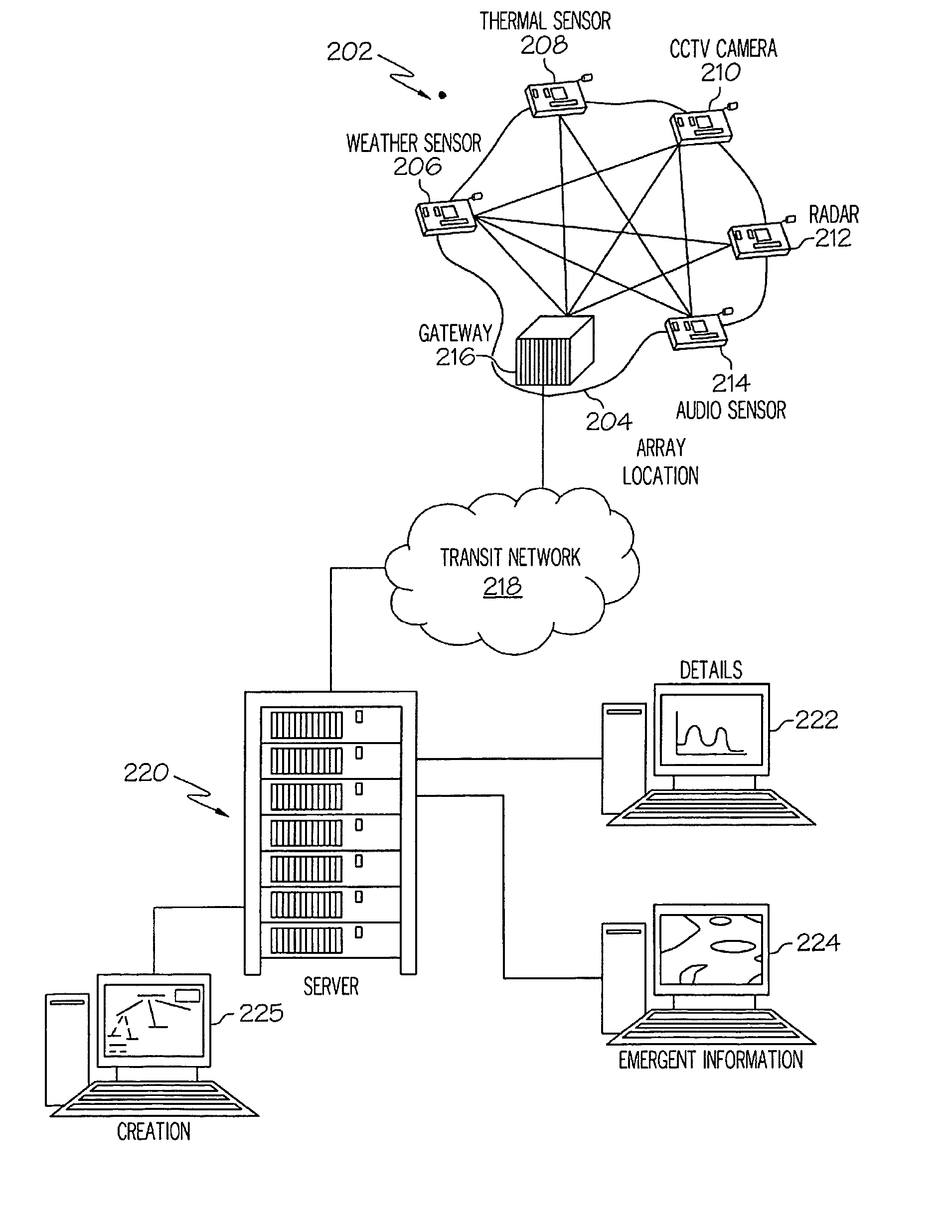
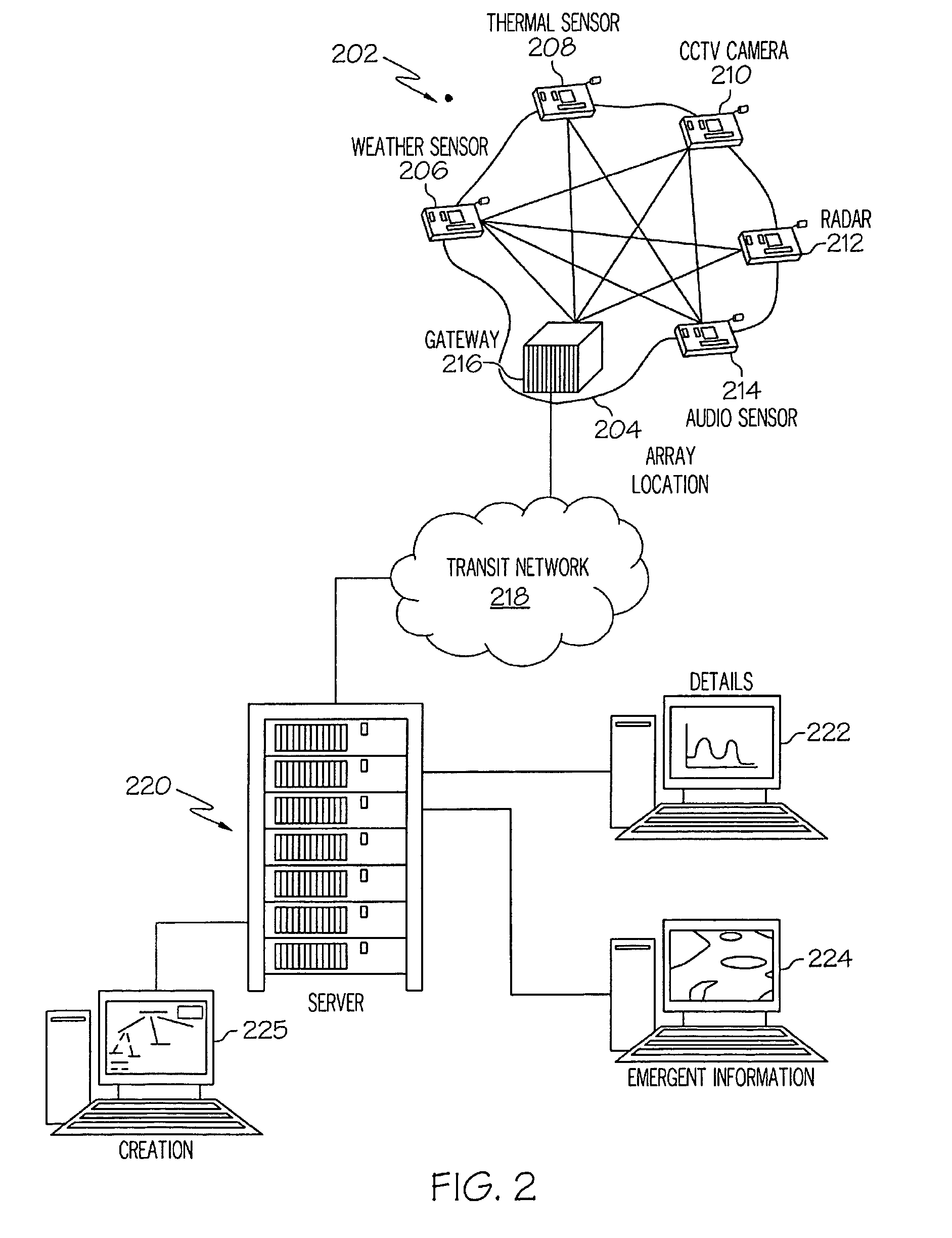
[0022]Presently presented is a hardware, software and process system for managing emergent information patterns from a sensor network through the use of graphical user-created patterns.

[0023]As described in detail below, a field of smart sensors, as used in the present invention, is interactive. A controlling software, which describes a set of search patterns for the field of sensors, is pre-programmed or downloaded to the field of sensors. Each sensor “votes” as to whether it has detected an external stimulus that fits in any of the search patterns stored within the sensor. As the “vote” tally reaches a high enough percentage of “opt-ins,” against a time line per pattern, the sensor field takes turns trying to get the results of the vote and its supporting details, already constantly shared amongst the sensors (e.g., by using a ZIGBEE™-type network—ZIGBEE is a registered trademark of the ZigBee Alliance in the United States and other countries), out via various telecommunications c...


PUM


Abstract

A method, system and computer program product for communicating pattern data is presented. A graphical event pattern is sent to an interconnected array of intelligent sensors. When intelligent sensors in the interconnected array determine that an event has occurred, the graphical event pattern is sent to a user. Thereafter, any data that supports the graphical event pattern is sent to the user. Thus, this supporting data is transmitted according to the graphical event pattern, rather than a header address.

Description

BACKGROUND OF THE INVENTION[0001]1. Technical Field[0002]The present disclosure relates to the field of detection networks and managing the emergent information that their sensors develop.[0003]2. Description of the Related Art[0004]Currently, system sensors and other detection processes and devices collect data in a non-intelligent manner. That, is, even if a sensor has limited intelligence (e.g., a camera that automatically tracks moving objects), most of the data collected by the sensors, and then transmitted to a controller, is meaningless. Furthermore, sensors typically transmit data in a continuous manner, such that most of the transmitted data is “dead air” in which nothing of interest is happening. To find subject matter of interest, the controller must perform manual data mining that is time consuming, and worse yet, does not enable the controller to recognize emergent information patterns that are obvious only in the context of a composite picture created by data from diff...

Claims


Application Information

Patent Timeline
Patent Type & Authority Patents(United States)
IPC IPC(8): G08B29/00
CPCG08B13/19667G08B25/14G08B31/00
Inventor MILLER, LANDON C. G.
Owner INT BUSINESS MASCH CORP
Why Eureka
Try Eureka