Internal UFD

a technology of ufd and panel, which is applied in the direction of electrical apparatus casing/cabinet/drawer, coupling device connection, instruments, etc., can solve the problems of cumbersome and risky handling of the host system while the ufd is plugged, increased risk of damage to both the host system and the ufd, and noticeable problem of ufd protruding from the panel

Inactive Publication Date: 2011-01-11
WESTERN DIGITAL ISRAEL LTD
View PDF37 Cites 21 Cited by
  • Summary
  • Abstract
  • Description
  • Claims
  • Application Information

AI Technical Summary

Benefits of technology

[0013]As the UFD in that preferred embodiment may be too small to be handled when not engaged in the host system, another preferred embodiment of the present invention includes a UFD holder configured to accommodate the small UFD when the UFD is outside the host system. This configuration enables the UFD to be safely and conveniently carried and used with other host systems. In a variation of this embodiment, the UFD holder connects to the small UFD at an end of the UFD holder, thus chancing the form factor of the combined UFD / UFD holder unit into the form factor of a standard UFD.
[0015]In another preferred embodiment of the present invention, when the UFD is engaged in the host panel, an ejection mechanism ejects the UFD out of the cavity of the host panel only when the host system is instructed by the user or by the host software. This mechanism serves two purposes. The mechanism eliminates untimely ejection of the UFD from the host panel during file transfer, and enables easy removal of the UFD from the host panel without using tools.
[0017]In another preferred embodiment of the present invention, the cavity of the host panel is configured to have at least one parallel alignment guide, and the UFD is configured to have a matching tunnel. Thus, when the UFD is inserted into the cavity, the UFD slides accurately into place as the UFD tunnel aligns with the cavity's alignment guide, ensuring a smooth engagement of the UFD plug into the USB socket.
[0018]In another preferred embodiment of the present invention, the USB socket of the host panel is recessed in the host panel cavity by an amount that is slightly more than the width of a typical UFD (typically 20 mm), and has a mechanism for rotating approximately 90 degrees in a vertical or horizontal plane. When a general-purpose UFD is plugged into a USB socket, the UFD typically protrudes beyond the contour of the host panel by an amount that is approximately the difference between the length of the UFD and the depth of the host panel cavity. After engaging the UFD in the USB socket, the user can rotate the UFD and the USB socket together to a position in which the major plane of the UFD is practically parallel to the major plane of the host panel, and is completely accommodated in the recess. An optional door or shutter can cover the recess in order to hide the UFD.

Problems solved by technology

In this configuration, however, the UFD alters the natural from factor of the host system, making it cumbersome and risky to handle the host system while the UFD is plugged in.
In addition, the protrusion of the UFD presents an increased risk of damage to both the host system and the UFD.
Furthermore, in situations where the aesthetic appearance of the host system is important, such as an expensive digital TV in a living room, the protrusion of the UFD from the panel is considered a noticeable problem as well.
This is practically impossible with the current state-of-the-art UFD.
This not only interferes with the aesthetic design of the device, but also creates a practical problem as the dongle may be accidentally pulled out or damaged by user passing by the device.
A easily-removable device protruding from a television is a both a safety hazard and a candidate for domestic vandalism.

Method used


Image

  • Internal UFD
  • Internal UFD
  • Internal UFD

Examples


Embodiment Construction

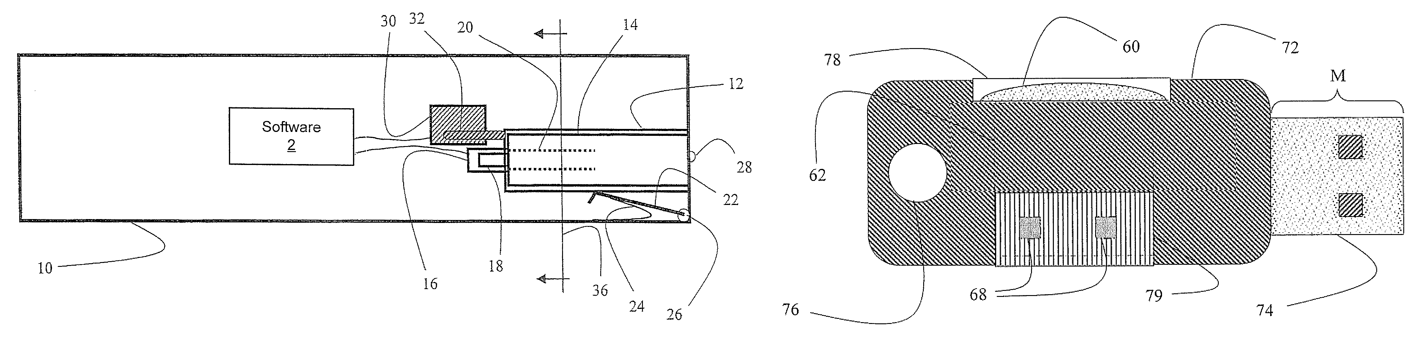
[0067]The present invention relates to systems and methods for accommodating an internal UFD in a host system such that the LTD does not protrude beyond the exterior of the host system. The principles and operation for an internal UFD, according to the present invention, may be better understood with reference to the accompanying description and the drawings.

[0068]Referring now to the drawings, FIG. 1 shows a cross-sectional view of a notebook computer having an internal UFD slot, according to a preferred embodiment of the present invention. A notebook computer 10, having a form factor similar to a ThinkPad™ computer (available from Lenovo™ Group Ltd, 1 Manhattanville Rd., Suite PH, Purchase, New York) is configured to have a deep recess 12, long enough to accommodate the full length of a UFD 14 (typically 4-7 cm). A USB socket 16 is installed in the inner wall of recess 12, accommodating a USB connector 18 of LTD 14. Longitudinal guide rails 20 (shown in phantom) on the side walls ...


PUM


Abstract

The present invention discloses a system including: (a) a host device including: (i) a cavity; and (ii) a socket, recessed in the cavity; and (b) a UFD configured to be reversibly operationally connected to the host device via the socket, wherein the UFD is configured to physically reside substantially in the cavity when the UFD is operationally connected to the socket. Also disclosed is a UFD system including: (a) a first part having components of a UFD, wherein the components include a primary connector and an electronics assembly; and (b) a second art having a UFD holder and a secondary connector, wherein the UFD holder is configured to reversibly accommodate the first part, wherein a dimension of the first part parallel to an insertion direction of the primary connector is shorter than a dimension of the second part parallel to an insertion direction of the secondary connector. In another embodiment, a UFD may be inserted into a UFD slot in an edge of a host panel.

Description

[0001]This patent application claims the benefit of U.S. Provisional Patent Application No. 60 / 803,050 filed May 24, 2006.FIELD AND BACKGROUND OF THE INVENTION[0002]The present invention relates to systems and methods for accommodating an internal UFD (USB flash disk) in a host system such that the UFD does not significantly protrude beyond the exterior of the host system.[0003]A UFD is a well-known device for portable data storage. A typical shape of a UFD resembles a short, straight, flat stick, making the UFD easy to grip by a user, hang on a key chain, and store in a pocket. When plugged into a lost system, typically a notebook computer or a digital TV, a prior alt UFD generally significantly protrudes beyond the exterior of the host system. The UFD typically protrudes perpendicular to the panel containing the USB socket.[0004]This configuration makes it easy to plug the UFD into the host, see that the UFD is plugged in, and unplug the UFD when desired. In this configuration, ho...

Claims


Application Information

Patent Timeline
Patent Type & Authority Patents(United States)
IPC IPC(8): H01R13/62
CPCH05K5/0278H01R13/4536H01R13/635Y10S439/945
Inventor ACHSAF, NITZANRAINES, MOSHEZEIGLER, ALONPOMERANTZ, ITZHAKL
Owner WESTERN DIGITAL ISRAEL LTD
Why Eureka
Try Eureka