Two-wire dimmer circuit for a screw-in compact fluorescent lamp

a compact fluorescent lamp and dimmer circuit technology, applied in the direction of electric variable regulation, process and machine control, instruments, etc., can solve the problems of inability to appropriately control the screw-in compact fluorescent lamp, flickering light output, audible noise, etc., and achieve the effect of preventing multiple firing of the controllably conductive switching devi

Inactive Publication Date: 2011-01-11
LUTRON TECH CO LLC
View PDF12 Cites 64 Cited by
  • Summary
  • Abstract
  • Description
  • Claims
  • Application Information

AI Technical Summary

Benefits of technology

[0012]According to the present invention, a two-wire dimmer control circuit for a dimmable screw-in compact fluorescent lamp load comprises a controllably conductive switching device, a phase-cut AC drive circuit, and a high-end intensity regulation circuit. The controllably conductive switching device has a control electrode and is adapted to be coupled in series electrical connection between an AC power source and a ballast circuit of the screw-in fluorescent lamp load. The phase-cut AC drive circuit is connected to the control electrode of the controllably conductive switching device for rendering the controllably conductive switching device conductive for a conductive interval each half-cycle of the AC power source. The phase-cut AC drive circuit is operable to control the length of the conduction interval of the controllably conductive switching device each half-cycle. The high-end intensity regulation circuit limits the length of the conduction interval of the controllably conductive switching device to less than approximately 75% of each half-cycle, thereby preventing multiple firings of the controllably conductive switching device.
[0013]The present invention further provides a phase-cut circuit for controlling the amount of power delivered from an AC power source to an incandescent lamp. The phase-cut circuit is modified to drive a fluorescent ballast for a fluorescent lamp. The phase-cut circuit includes a triac that has a lower holding current than that used for the incandescent lamp, and provides a reduced high end as compared to that used for the incandescent lamp.
[0014]According to another embodiment of the present invention, a two-wire dimmer circuit for a fluorescent lamp load comprises a bi-directional semiconductor switch, a timing circuit, and a trigger circuit for rendering the bi-directional semiconductor switch conductive for a conduction interval each half-cycle, where the improvement comprises the timing circuit being adapted to limit the conduction interval to less than approximately 75% of each half-cycle. The bi-directional semiconductor switch is adapted to be coupled in series electrical connection between the AC power source and a ballast circuit of the fluorescent lamp for controlling the amount of power delivered to the ballast circuit. The timing circuit is operatively coupled in parallel electrical connection with the bi-directional semiconductor switch, and has an output for generating a timing voltage representative of a desired intensity of the fluorescent lamp. The trigger circuit is operatively coupled between the output of the timing circuit and a control input of the bi-directional semiconductor switch. The trigger circuit is operable to render the bi-directional semiconductor switch conductive in response to the timing voltage, such that the bi-directional semiconductor switch is conductive for the conduction interval each half-cycle.

Problems solved by technology

Since the screw-in compact fluorescent lamps have different operational characteristics than incandescent lamps, the dimmer circuits used for the screw-in incandescent lamps (as shown in FIG. 1) are not able to appropriately control the screw-in compact fluorescent lamps.
These multiple firings of the semiconductor switch can cause flicker in the light output, audible noise, increased electro-magnetic interference (EMI), and excessive stress on the components of the dimmer circuit 20 and the ballast circuit 36 of the screw-in fluorescent lamp.
As a result, the dimming of compact fluorescent lamps has been commercially unsuccessful thus reducing the possibility of further energy savings with these desirable replacements for energy-wasting incandescent lamps.

Method used


Image

  • Two-wire dimmer circuit for a screw-in compact fluorescent lamp
  • Two-wire dimmer circuit for a screw-in compact fluorescent lamp
  • Two-wire dimmer circuit for a screw-in compact fluorescent lamp

Examples


first embodiment

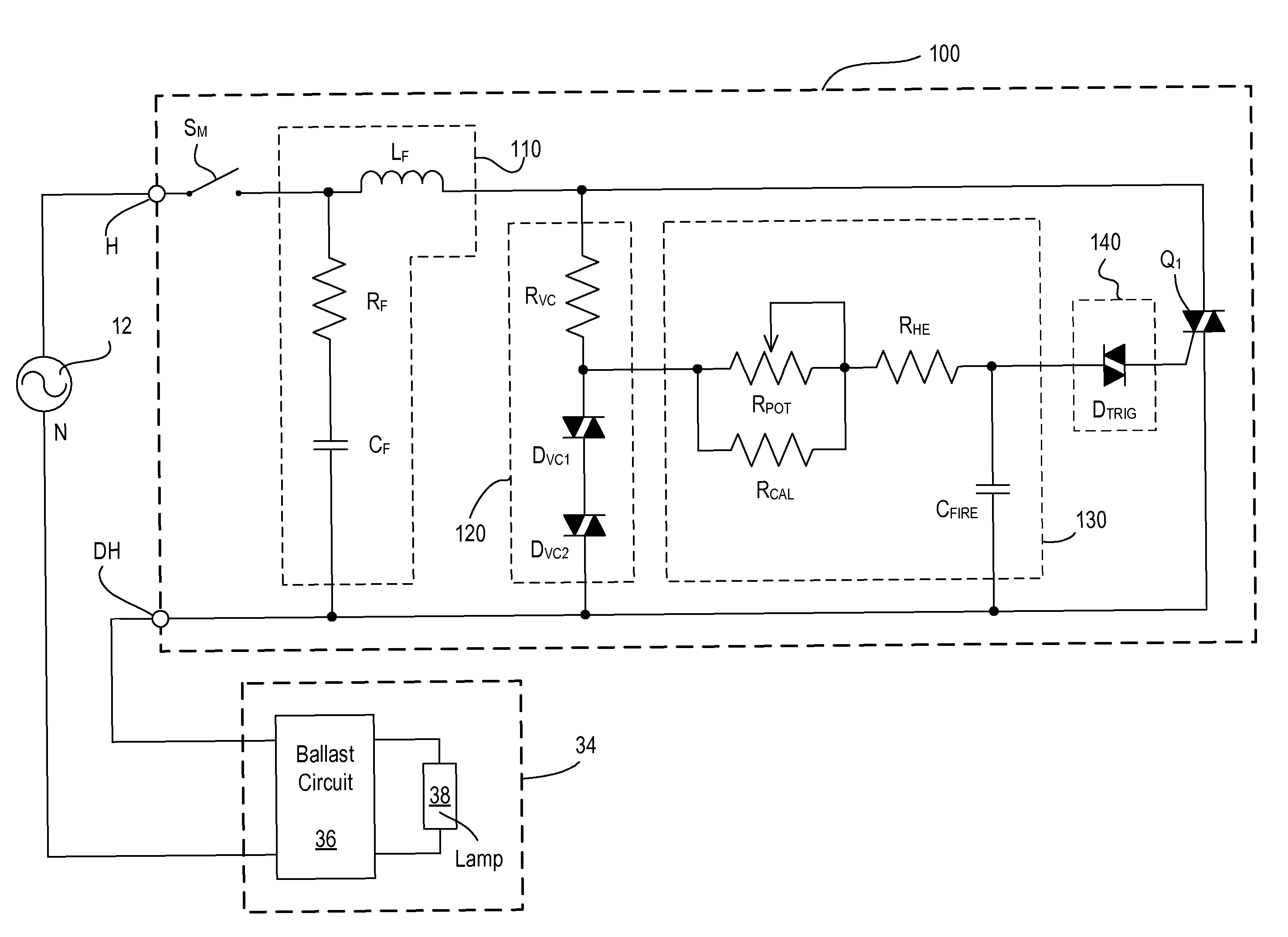
[0053]FIG. 7 is a simplified diagram of a dimmer switch 100 (i.e., a dimmer circuit) for controlling the amount of power delivered to the dimmable screw-in compact fluorescent lamp 34 according to the present invention. Particularly, the dimmer switch 100 of the present invention is able to control the intensity of the dimmable screw-in compact fluorescent lamp 34 to the high-end intensity setting while avoiding multiple firings. It was discovered that reducing the conduction interval TCON by approximately 0.6 msec near the high-end intensity setting of the dimmer switch 100 did not visibly change the light output of the fluorescent lamp 38, but eliminated the problem of multiple firings. When controlling an incandescent lamp (as with the prior art dimmer circuit 10) or a two-wire ballast (as with the prior art dimmer circuit 20), it is desirable to maximize the conduction interval TCON to provide the maximum possible light output of the connected lighting load at the high-end inten...

second embodiment

[0068]FIGS. 11 and 12 are perspective views of a user interface of a dimmer switch 200 according to the present invention. The dimmer switch 200 includes a user-accessible operating mode adjustment actuator 250 that allows a user to change the dimmer switch 200 between an incandescent load operating mode and a screw-in compact fluorescent load operating mode. When the operating mode adjustment actuator 250 is in a first position, the dimmer switch 200 operates in the incandescent load operating mode. Accordingly, the high-end intensity setting of the dimmer switch is adjusted to a first high-end intensity setting value and the low-end intensity setting is adjusted to a first low-end intensity setting value. When the operating mode adjustment actuator 250 is in a second position, the dimmer switch 100 operates in the screw-in compact fluorescent load operating mode, such that the high-end intensity setting is adjusted to a second high-end intensity setting value and the low-end inten...

third embodiment

[0074]FIG. 14 is a front view of a user interface 301 of a “smart” dimmer switch 300 according to the present invention. The dimmer switch 300 comprises a control actuator 302 and an intensity adjustment actuator 304 (i.e., a rocker switch). An actuation of the control actuator 302 causes the dimmer switch 300 to toggle the lighting load 202 between on and off. An actuation of the upper portion 304A of the intensity adjustment actuator 304 raises the light intensity of the lighting load 202, while an actuation of the lower portion 304B of the intensity adjustment actuator lowers the light intensity. The control actuator 302 and the intensity adjustment actuator 304 are provided on the front surface of a bezel 305, which is received in the opening of a faceplate 306. An air-gap switch actuator 309 actuates an internal mechanical switch SAG (FIG. 15) to provide an actual air-gap break between the AC power source 12 and the lighting load 202.

[0075]The dimmer switch 300 also includes a ...


PUM


Abstract

A dimmer switch for controlling the intensity of a dimmable screw-in compact fluorescent lamp provides smooth dimming of the fluorescent lamp and prevents flickering of the lamp due to multiple re-strikes. The dimmer switch prevents multiple re-strikes by avoiding multiple firings of a controllably conductive switching device of the dimmer circuit by limiting the high-end light intensity of the fluorescent lamp. Specifically, the dimmer switch limits the length of a conduction interval of the controllably conductive switching device to less than approximately 75% of each half-cycle. The dimmer switch may include a user-accessible adjustment actuator for changing the dimmer switch between an incandescent operating mode and a screw-in compact fluorescent mode. The dimmer switch may also be operable to automatically change the dimmer switch between the incandescent operating mode and the screw-in compact fluorescent mode by detecting the occurrence of the multiple firings of the controllably conductive switching device.

Description

BACKGROUND OF THE INVENTION[0001]1. Field of the Invention[0002]The present invention relates to load control devices for controlling the amount of power delivered to an electrical load from a power source. More specifically, the present invention relates to a two-wire dimmer circuit for controlling the intensity of a dimmable screw-in compact fluorescent lamp.[0003]2. Description of the Related Art[0004]A conventional two-wire dimmer circuit 10, as shown in FIG. 1, has two terminals: a “hot” terminal H for connection to an alternating-current (AC) power source 12 (e.g., 120 VAC@60 Hz) and a “dimmed hot” terminal DH for connection to a lighting load 14, such as an incandescent lamp. The dimmer circuit 10 typically uses a bi-directional semiconductor switch (not shown), such as, for example, a triac, to control the current delivered to the lighting load 14, and thus to control the state (i.e., on or off) and the intensity of the lighting load between a high-end intensity setting (i.e...

Claims


Application Information

Patent Timeline
Patent Type & Authority Patents(United States)
IPC IPC(8): H05B41/36
CPCH05B39/08H05B41/3924Y10S315/04Y02B20/19Y02B20/00
Inventor WEIGHTMAN, RUSSELLTAIPALE, MARK S.
Owner LUTRON TECH CO LLC
Why Eureka
Try Eureka