Two-wire dimmer circuit for a screw-in compact fluorescent lamp
a compact fluorescent lamp and dimmer circuit technology, applied in the direction of electric variable regulation, process and machine control, instruments, etc., can solve the problems of inability to appropriately control the screw-in compact fluorescent lamp, flickering light output, audible noise, etc., and achieve the effect of preventing multiple firing of the controllably conductive switching devi
- Summary
- Abstract
- Description
- Claims
- Application Information
AI Technical Summary
Benefits of technology
Problems solved by technology
Method used
Image
Examples
first embodiment
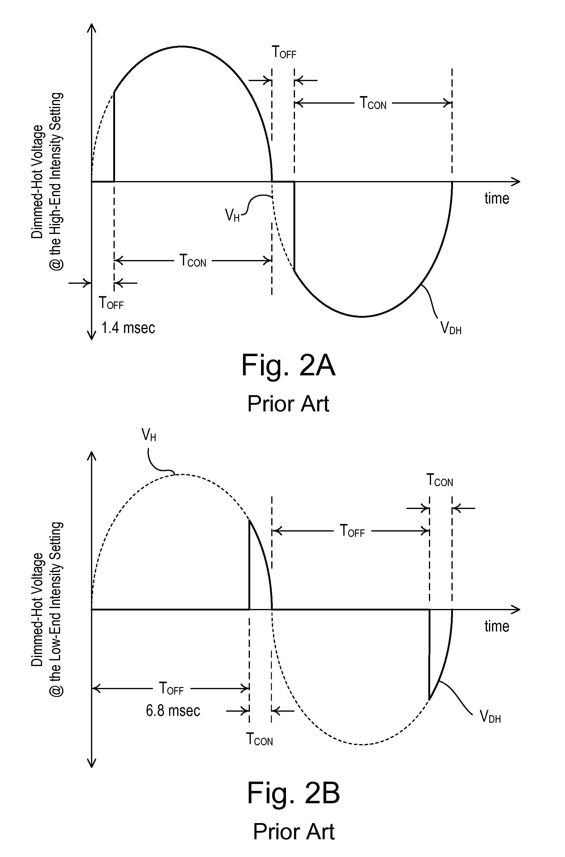
[0053]FIG. 7 is a simplified diagram of a dimmer switch 100 (i.e., a dimmer circuit) for controlling the amount of power delivered to the dimmable screw-in compact fluorescent lamp 34 according to the present invention. Particularly, the dimmer switch 100 of the present invention is able to control the intensity of the dimmable screw-in compact fluorescent lamp 34 to the high-end intensity setting while avoiding multiple firings. It was discovered that reducing the conduction interval TCON by approximately 0.6 msec near the high-end intensity setting of the dimmer switch 100 did not visibly change the light output of the fluorescent lamp 38, but eliminated the problem of multiple firings. When controlling an incandescent lamp (as with the prior art dimmer circuit 10) or a two-wire ballast (as with the prior art dimmer circuit 20), it is desirable to maximize the conduction interval TCON to provide the maximum possible light output of the connected lighting load at the high-end inten...
second embodiment
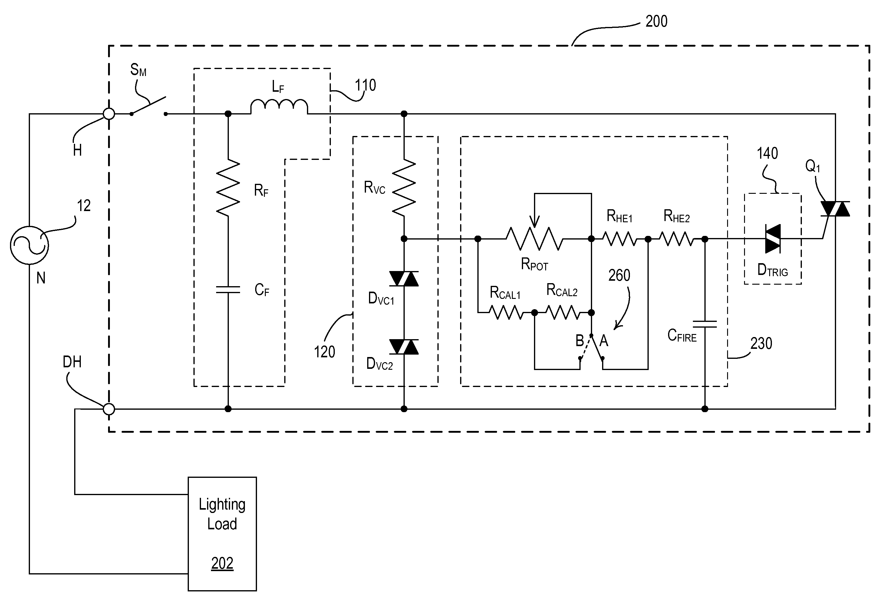
[0068]FIGS. 11 and 12 are perspective views of a user interface of a dimmer switch 200 according to the present invention. The dimmer switch 200 includes a user-accessible operating mode adjustment actuator 250 that allows a user to change the dimmer switch 200 between an incandescent load operating mode and a screw-in compact fluorescent load operating mode. When the operating mode adjustment actuator 250 is in a first position, the dimmer switch 200 operates in the incandescent load operating mode. Accordingly, the high-end intensity setting of the dimmer switch is adjusted to a first high-end intensity setting value and the low-end intensity setting is adjusted to a first low-end intensity setting value. When the operating mode adjustment actuator 250 is in a second position, the dimmer switch 100 operates in the screw-in compact fluorescent load operating mode, such that the high-end intensity setting is adjusted to a second high-end intensity setting value and the low-end inten...
third embodiment
[0074]FIG. 14 is a front view of a user interface 301 of a “smart” dimmer switch 300 according to the present invention. The dimmer switch 300 comprises a control actuator 302 and an intensity adjustment actuator 304 (i.e., a rocker switch). An actuation of the control actuator 302 causes the dimmer switch 300 to toggle the lighting load 202 between on and off. An actuation of the upper portion 304A of the intensity adjustment actuator 304 raises the light intensity of the lighting load 202, while an actuation of the lower portion 304B of the intensity adjustment actuator lowers the light intensity. The control actuator 302 and the intensity adjustment actuator 304 are provided on the front surface of a bezel 305, which is received in the opening of a faceplate 306. An air-gap switch actuator 309 actuates an internal mechanical switch SAG (FIG. 15) to provide an actual air-gap break between the AC power source 12 and the lighting load 202.
[0075]The dimmer switch 300 also includes a ...
PUM
 Abstract
Description
Claims
Application Information
 - R&D
- Intellectual Property
- Life Sciences
- Materials
- Tech Scout
- Unparalleled Data Quality
- Higher Quality Content
- 60% Fewer Hallucinations
Browse by: Latest US Patents, China's latest patents, Technical Efficacy Thesaurus, Application Domain, Technology Topic, Popular Technical Reports.
© 2025 PatSnap. All rights reserved.Legal|Privacy policy|Modern Slavery Act Transparency Statement|Sitemap|About US| Contact US: help@patsnap.com


