Tensioner with reinstallation feature

a technology of reinstallation and tensioner, which is applied in the direction of belt/chain/gearing, mechanical equipment, belts, etc., can solve the problems of the total return of the tensioner arm, the serious drawback, and the return torque required to rotate the arm away from the belt, so as to prevent the excessive opening of the clutch spring coil, restrict the radial vibration of the spring coil, and limit the distortion and vibration of the spring

Active Publication Date: 2011-01-25
LITENS AUTOMOTIVE INC
View PDF23 Cites 31 Cited by
  • Summary
  • Abstract
  • Description
  • Claims
  • Application Information

AI Technical Summary

Benefits of technology

[0018]The present invention provides a tensioner that allows easy and reliable reinstallation of the tensioner and belt in the field service while simultaneously making it possible to use one-way clutch device to allow easy and continuous belt tension control without cumbersome manual alignment and / or realignment procedures.
[0020]It is further desirable to provide a support for the force carrying tang of the spring type one-way clutch to avoid excessive bending or yielding when the clutch acts as a backstop preventing the arm movement away from the belt.
[0021]It is further desirable to provide a design that isolates the clutch from the sudden short time vibratory movements of the tensioner arm so that the one-way clutch is not rotated when the arm is traveling in its path away from the cold engine position.
[0022]It is further desirable to provide a low noise tensioner by eliminating metal to metal contact in the arm stops during the running of the engine.
[0023]It is further desirable to introduce into the tensioner features that limit excessive spring distortion and vibration therefore avoiding spring fatigue failures.
[0027]According to another aspect of the invention there is provided the spring clutch is encapsulated by clutch sleeve that will prevent the excessive opening of the clutch spring coils. This clutch sleeve is preferably made out of plastic or elastomer type material and can be formed also to support the load carrying tang of the clutch spring as well as to isolate any direct metal to metal contact between the tensioner arm and the clutch spring. Both of the above-mentioned embodiments can further have two distinctive features to limit the distortion and vibration of the spring. The first one is to form at least one end, but preferably both ends, of the spring cavity as helix which closely matches the theoretical pitch of the spring coils at their nominal or near nominal position. The second one is to provide a spring support that will extend at least a half length of the spring cavity to restrict the radial vibration of the spring coils. The anti-vibration spring support is preferable made of plastic or elastomer type materials to reduce the wear and the noise of the spring.

Problems solved by technology

All of the above mentioned designs, even if they allow some limited return stroke to compensate thermal expansion of the engine block, do not allow a total return of the tensioner arm to pre-installation position, which will be required if there is a need to reinstall the current belt after a field service or even more so, if the installation of a new, unstretched belt is required.
All of these designs have a serious drawback, since the return torques required to rotate the arm away from the belt are very high.
In case of forcing the viscous clutch, if the turning speed is not very slow, the operator is most likely to damage some components in the tensioner.
On the other hand, the reverse movement of a simple spring clutch, as described in U.S. Pat. No. 4,917,655, is most likely to result in bent spring tangs rather than release of the clutch.
This is due to the fact that spring clutches are extremely sensitive to the manufacturing tolerances of the spring wire, the spring coils and the shaft diameter as well the level of the coefficient of friction which is highly unpredictable especially in dusty engine compartment environment in used, older cars.
For the same reason, this particular design cannot properly control the exact angular return stroke since, depending on the actual release torque of the clutch spring towards the belt tightening direction, the spring tang and the first two coils adjacent to this tang are bending and opening unpredictably therefore changing the actual stroke angle between the stops.
However, this design, similarly to the three above-mentioned ones, requires a multitude of expensive, high precision components which also increase the size and the weight of the tensioner, all this highly undesirable in modern motor car engines.
This design also has the disadvantage of not controlling the release torque well enough.
While the use of one-way clutches together with the built-in limited thermal expansion stroke features have made it possible to simultaneously use the main spring to automatically take care of the installation stroke and to extend the overall operation range of the tensioners thereby allowing longer belt stretch, this design concept has introduced another so far unsolved technical problem.
These spring designs have a distinctive drawbacks, the natural frequency of the spring gets lower and springs are easily distorted when wound with large preload angles.
This, on the other hand, make the springs much more suspect for excessive vibrations during the service leading to premature fatigue failures of the spring resulting in damaged engines.

Method used


Image

  • Tensioner with reinstallation feature
  • Tensioner with reinstallation feature
  • Tensioner with reinstallation feature

Examples


Embodiment Construction

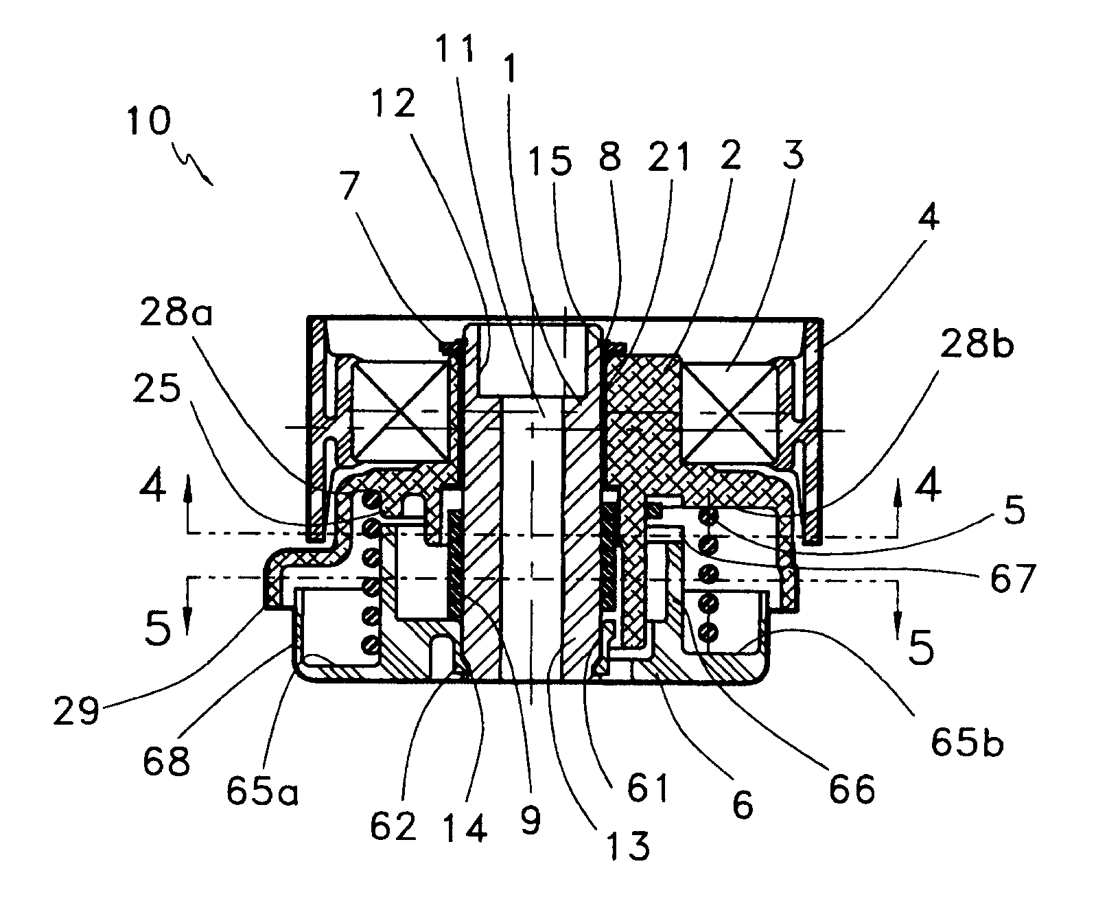
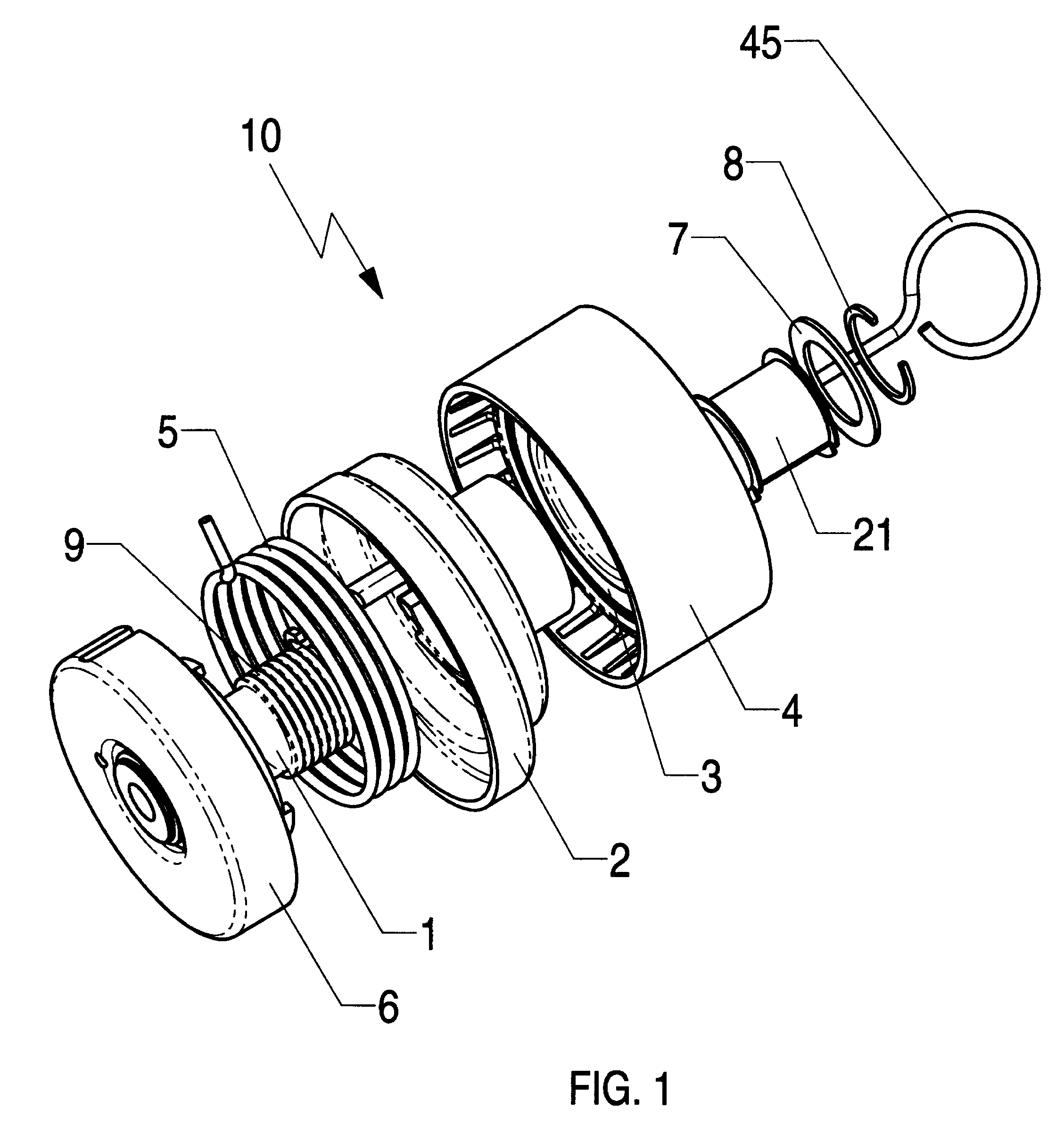
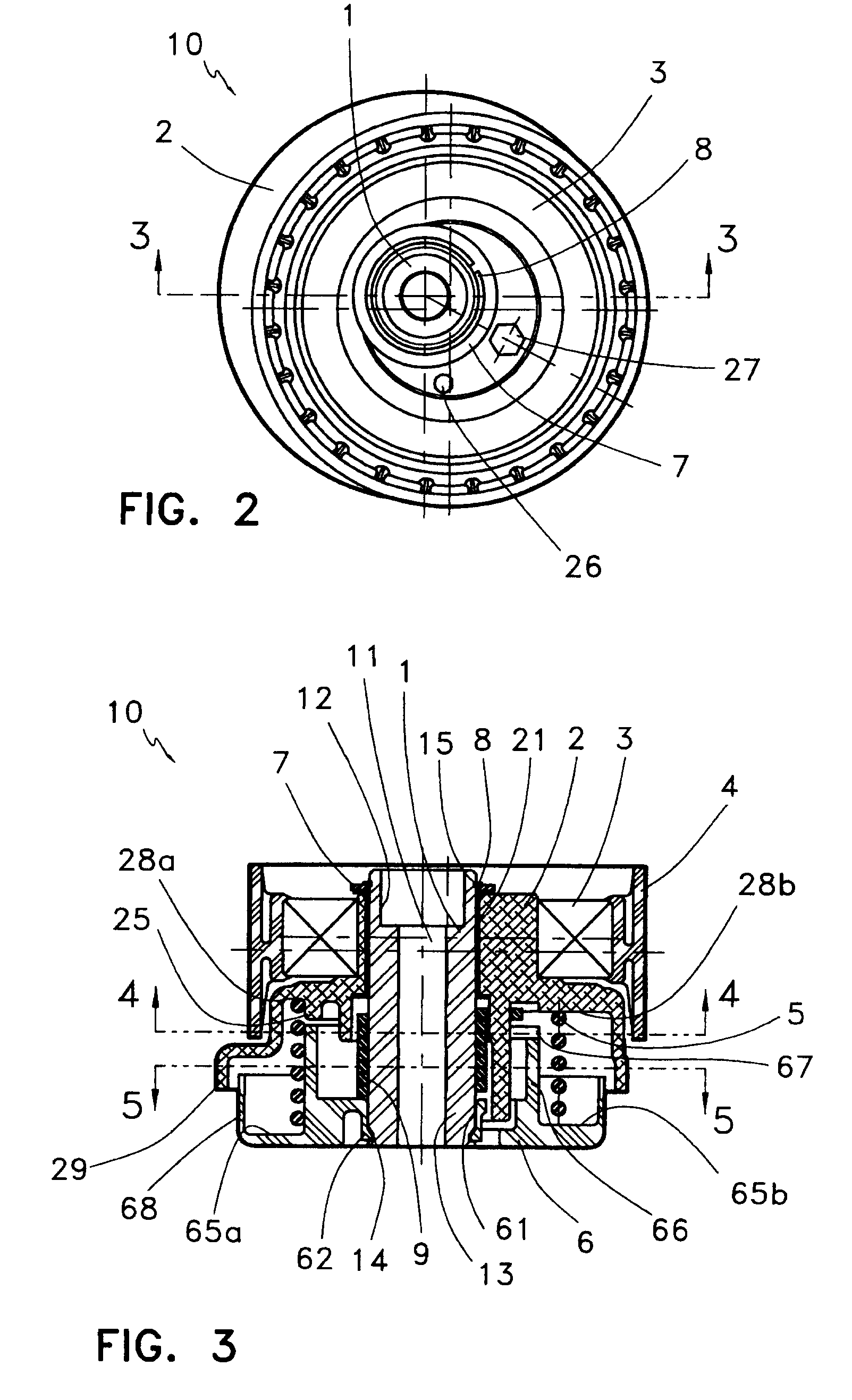
[0036]A tensioner in accordance with the present invention is indicated generally at 10 in FIGS. 1 and 3. As shown, the tensioner 10 comprises a pivot shaft 1, arm 2 including a pivot bushing 21 rotationally mounted about the pivot shaft 1, a bearing 3 mounted on the arm 2 carrying a pulley 4, a main spring 5, a base cup 6, a top washer 7, a lock ring 8 and a clutch spring 9.

[0037]The pivot bushing 21 allows the arm 2 rotate about the centre axis of the pivot shaft 1 while being biased towards the belt (not shown) by the main spring 5 mounted between the arm 2 and the base cup 6 and / or a corresponding spring tang mounting slot in the engine (not shown). The top washer 7, while being prohibited to move axially out from the pivot shaft 1 by the lock ring 8, placed into a ring groove 15 of the pivot shaft 1, will prevent the arm 2 moving out of its position on and around the pivot shaft 1. The arm 2 also has a tooling hole 27 formed on its top face to allow the arm 2 being rotated away...


PUM


Abstract

A tensioner enables easy and reliable reinstallation of the tensioner and belt in the field service while simultaneously making it possible to utilize a one-way clutch device to ensure continuous belt tension control without cumbersome manual alignment and / or realignment procedures. The tensioner has a pivot shaft configured for mounting on an engine surface. A tensioner arm is mounted on the pivot shaft for pivotal movement between a free arm stop position and premount stop position. A belt-engaging pulley is mounted for rotation on the tensioner arm. A base cup is rotatably mounted around an end of the pivot shaft. The base cup has an arcuate slot having a free arm stop end and a premount stop end. The tensioner arm cooperates with the arcuate slot limiting the pivotal movement of the tensioner arm. A spring is coupled between the tensioner arm and the base cup biasing the tensioner arm in a belt-tensioning direction. An anti-kickback stop mechanism engages the pivot shaft and has a lost motion connection with the tensioner arm wherein the tensioner arm moves through a free range without engaging the anti-kickback mechanism. The tensioner arm 1) rotates the anti-kickback mechanism as the tensioner arm moves beyond the free range towards the premount stop position and 2) enables the anti-kickback mechanism as the tensioner arm moves beyond the free range towards the free arm stop position, limiting travel of the tensioner arm therebeyond. The spring is fixable relative to the pivot shaft upon the tensioner being mounted on the engine surface.

Description

FIELD OF THE INVENTION[0001]The present invention relates to a tensioning devices for maintaining an approximate, predetermined optimum tension on endless drive belts, which may be toothed, for use with internal combustion engine drive systems and more particularly to spring-biased eccentric devices which have one-way mechanism to control the movement of the tensioning arm towards and away from the belt directions.BACKGROUND OF THE INVENTION[0002]There are several known tensioner designs where the tensioner arm movement towards the drive belt is controlled with a one-way mechanism. U.S. Pat. No. 4,145,934 describes a wedge that is pushed against the arm eccentric (lever) so that latter cannot rotate outwards once the tensioner arm is biased towards the belt by a tensioning spring.[0003]U.S. Pat. No. 4,351,636 describes a tensioner similar in principle except that the one-way wedge is replaced by a ratchet / pawl assembly.[0004]Another ratchet and pawl mechanism is described in U.S. Pa...

Claims


Application Information

Patent Timeline
Patent Type & Authority Patents(United States)
IPC IPC(8): F16H7/12
CPCF16H7/1281F16H7/0848F16H2007/0878F16H2007/0846F16H2007/081F16H7/08F16H7/12
Inventor LEHTOVAARA, JORMA J.FRANKOWSKI, MAREK
Owner LITENS AUTOMOTIVE INC
Why Eureka
Try Eureka