Mass flow controller

a flow controller and controller technology, applied in fluid pressure control, process and machine control, instruments, etc., can solve the problem that the speed of response following the change of the flow rate setting value (the speed of response) cannot be sacrificed to suppress the excessive response described, and achieve the effect of sacrificing the speed of respons

Active Publication Date: 2011-02-01
HORIBA STEC CO LTD
View PDF20 Cites 28 Cited by
  • Summary
  • Abstract
  • Description
  • Claims
  • Application Information

AI Technical Summary

Benefits of technology

[0033]As described above, according to the present invention, since the mass flow controller switches the control between the stable period and the changing period, the mass flow controller can suppress a flow rate change without sacrificing the speed of response to a change of the flow rate setting value even if a pressure change occurs and can be applied to a system that may generate a disturbance such as a crosstalk. Furthermore, even if the pressure change occurs in the stable period in which a flow rate change due to a pressure change particularly becomes a problem, the actual flow rate can be further stabilized against the pressure change, because the value control is performed based on the opening control signal determined by the calculation formula including at least the flow rate measurement value and the flow rate setting value as well as the pressure value obtained by the pressure sensor section.

Problems solved by technology

However, under the current circumstance in which higher speed and precision are needed in the control of the raw material gas or the like used in semiconductor processes, the speed of following the change of the flow rate setting value (the speed of response) cannot be sacrificed to suppress the excessive response described above.Patent Document 1 Japanese Patent Laid-Open No. 2004-280689

Method used


Image

  • Mass flow controller
  • Mass flow controller
  • Mass flow controller

Examples


first embodiment

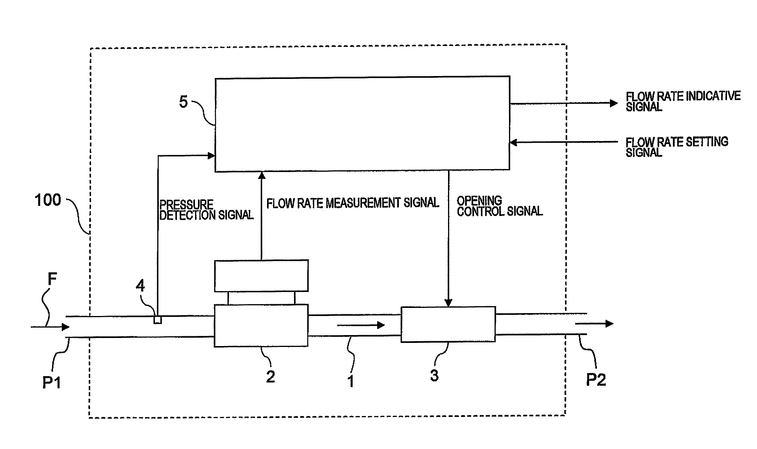
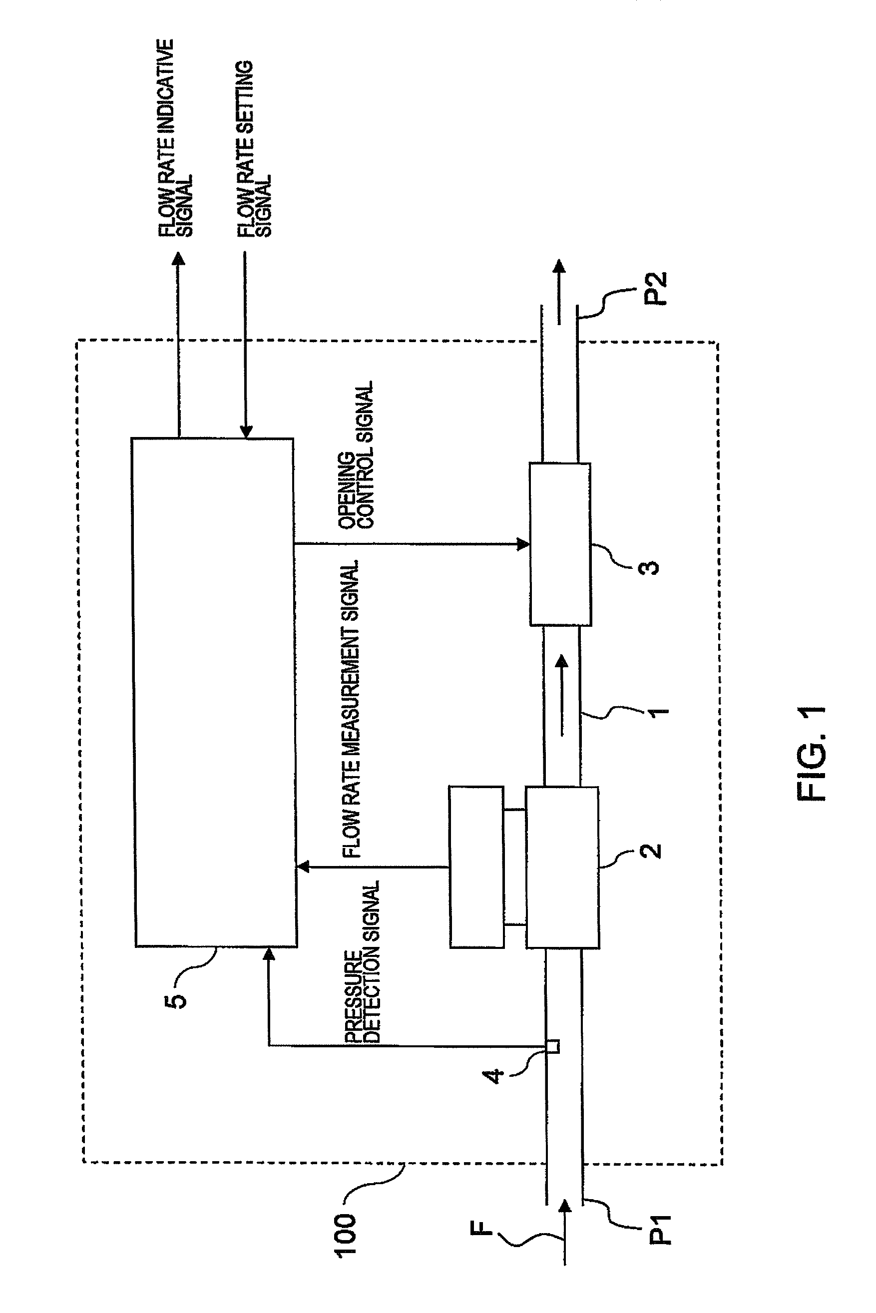
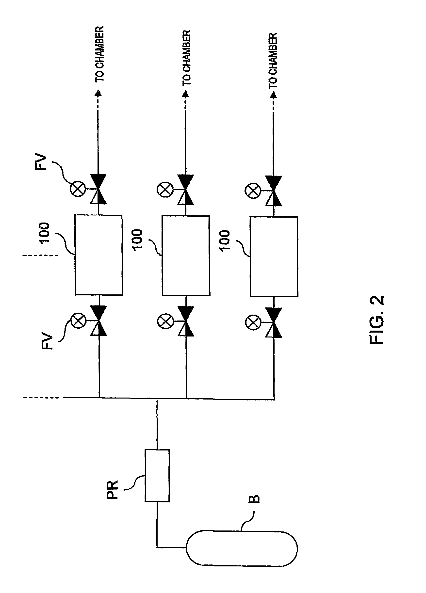
[0045]As shown in the schematic diagram of FIG. 1, a mass flow controller 100 according to an embodiment of the present invention comprises an internal channel 1, a flow rate sensor section 2 that measures the flow rate of a fluid F flowing through the internal channel 1, a flow rate control valve 3 disposed on, for example, a downstream side of the flow rate sensor section 2, a pressure sensor section 4 disposed on, for example, an upstream side of the flow rate sensor section 2 and a control section 5. The mass flow controller 100 is used, for example, in a gas supply system that supplies gas to a chamber in a semiconductor process as shown in FIG. 2.

[0046]Now, each component will be described. The internal channel 1 has an inlet port P1 on the upstream side and an outlet port P2 on the downstream side. For example, the inlet port P1 is connected to a fluid supply source B, such as a cylinder, via an external pipe, and the outlet port P2 is connected to a chamber (not shown in dra...

second embodiment

[0089]In the above-mentioned first embodiment, the deviation calculating section 5c1 calculates the deviation of the flow rate measurement value from the flow rate setting value, however, it is not limited to this, and the deviation between the flow rate measurement value or the corrected flow rate measurement value and the flow rate setting value or the corrected flow rate setting value may be calculated.

[0090]Now, the second embodiment, wherein the deviation calculating section 51c1 calculates the deviation of the value obtained by correcting the flow rate measurement value by the use of the pressure value from the flow rate setting value, will be described with reference to FIG. 5.

[0091]In FIG. 5, the same parts as those in the first embodiment are denoted by the same reference numerals as those in the embodiment, and descriptions thereof will be omitted. In the following, only differences from the first embodiment will be described.

[0092]The deviation calculating section 51c1 fi...

third embodiment

[0113]The adjusting factor X is set to be a constant value for the formula (5) in the second embodiment, however, the adjusting factor X is set to vary depending on a situation in the third embodiment. The functional block diagram of the third embodiment is omitted to draw because it is the same as that (the same as FIG. 5) of the second embodiment.

[0114]Specifically, the adjusting factor X is varied in accordance with the following formulas (7), (8).

[0115]In the stable period,

X=Q1+Q2·S  (7)

[0116]In the changing period,

X=Q1s+Q2s·S  (8)

[0117]In those formulas, the reference characters Q1, Q2, Q1s, Q2s denote adjusting factors, and the reference character S denotes the flow rate setting value.

[0118]Then by setting the adjusting factors appropriately, X increases at least as the flow rate setting value is smaller both in the changing period and in the stable period. This is because the smaller the flow rate setting value is, the more susceptible to the pressure change so that a stronge...


PUM


Abstract

This invention provides a mass flow controller that can prevent a flow rate change due to a pressure change without sacrificing the speed of response to a change of a flow rate setting value and can be used in a system that can generate a crosstalk.In order to provide the mass flow controller, the mass flow controller has: a control section 5 that calculates an opening control signal to be supplied to a flow rate control valve based on a predetermined calculation formula including at least a flow rate measurement value and a flow rate setting value as parameters and outputs the opening control signal; and a pressure sensor section 4 that measures pressure of a fluid on the upstream side or the downstream side of a flow rate sensor section 2 and outputs a pressure detection signal indicating the pressure value. The control section 5 uses different calculation formulas for a changing period, which is a predetermined period from a point in time when the flow rate setting value changes by a predetermined amount or more, and a stable period, which is the remaining period, and at least in the stable period, the calculation formula further includes the pressure value as a parameter.

Description

FIELD OF THE ART[0001]The present invention relates to a mass flow controller that controls a flow rate of a fluid, such as gas and liquid.BACKGROUND ART[0002]For example, in a semiconductor manufacturing apparatus to which various kinds of gas used for manufacturing a semiconductor are supplied, a mass flow controller is provided for each gas supply channel to adjust the flow rate of the gas. Conventionally, a pressure regulator is connected in series to each mass flow controller for preventing an extreme change in pressure in the channel to which the mass flow controller is attached, thereby facilitating flow rate control.[0003]A basic flow rate control method for the mass flow controller is the PID control. For example, there has been known a feed back control based on a variation of the PID control disclosed in the patent document 1. Specifically, according to the method disclosed in the patent document 1, the feed back control value is calculated by performing a PID calculation...

Claims


Application Information

Patent Timeline
Patent Type & Authority Patents(United States)
IPC IPC(8): G05D7/06G05D16/20
CPCG01F1/6965G05D7/0635G01F15/024G01F15/005Y10T137/2703Y10T137/7759G05D7/06
Inventor YONEDA, YUTAKATAKAHASHI, AKITO
Owner HORIBA STEC CO LTD
Why Eureka
Try Eureka