

Solar pump systems and related methods
a solar energy and pump technology, applied in the direction of positive displacement liquid engines, pumping, lighting and heating apparatus, etc., can solve the problems of prohibitively expensive, inefficient devices for converting solar energy to useable energy, and limited water resources
- Summary
- Abstract
- Description
- Claims
- Application Information
AI Technical Summary
Benefits of technology
Problems solved by technology
Method used
Image

Examples
Embodiment Construction
[0001]1. Field of the Invention
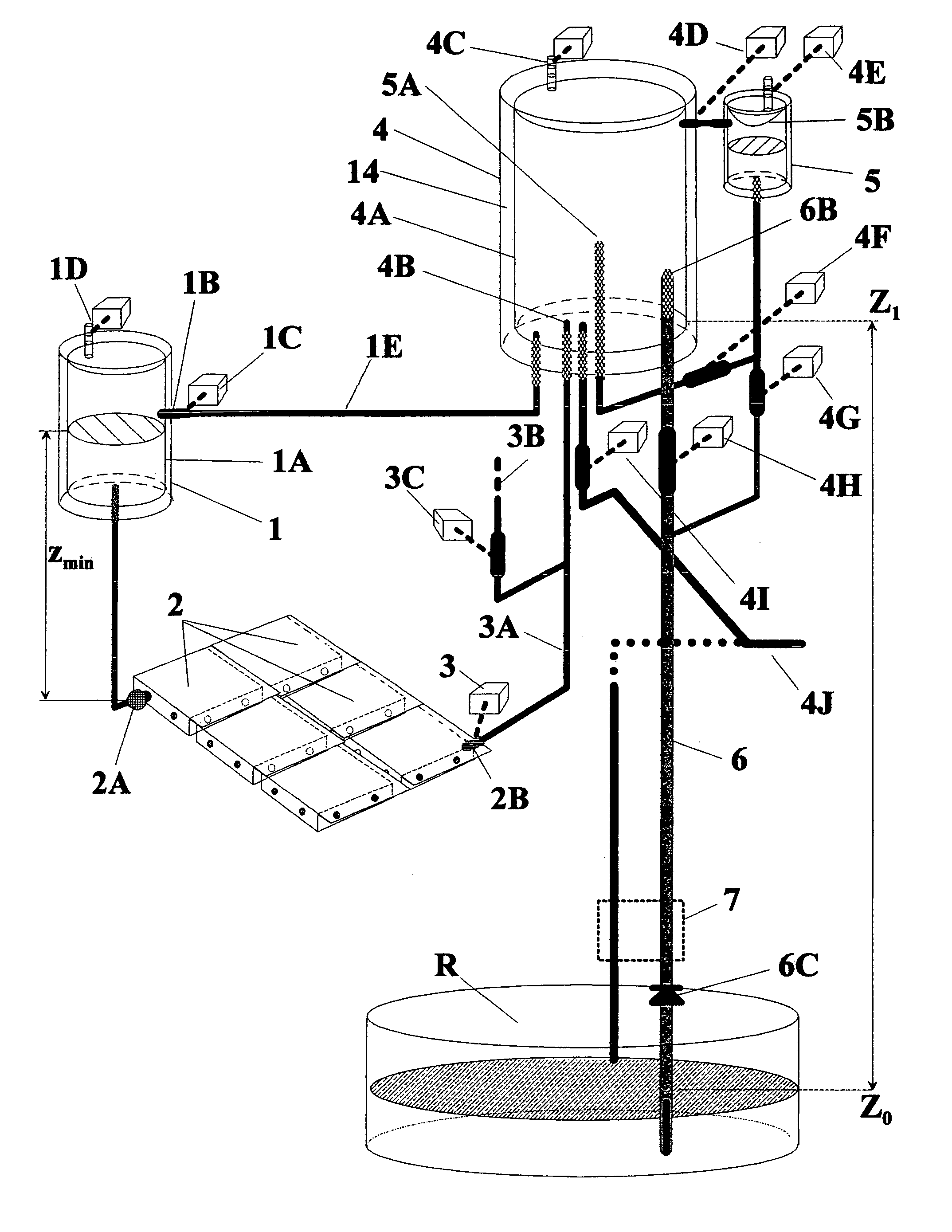
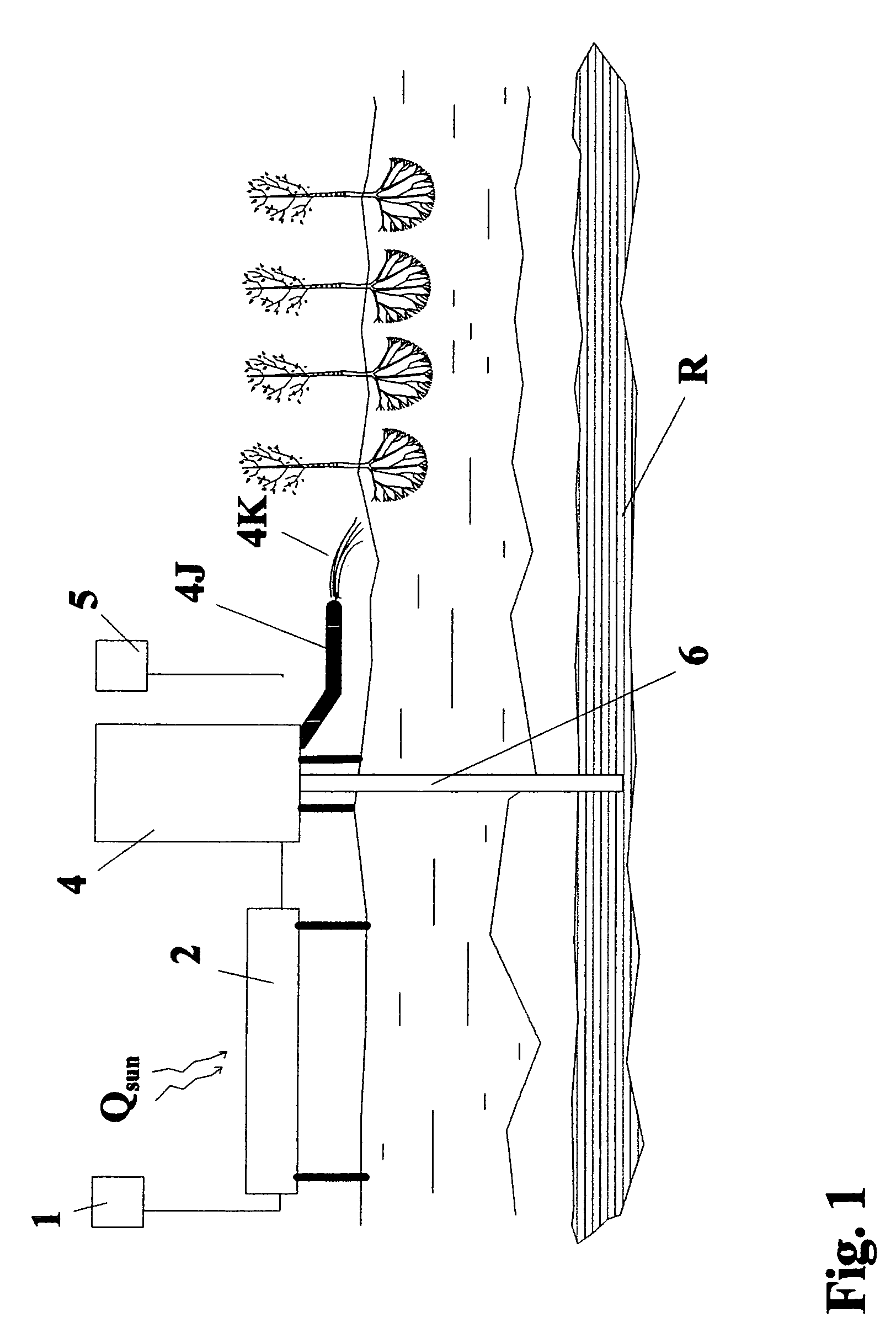
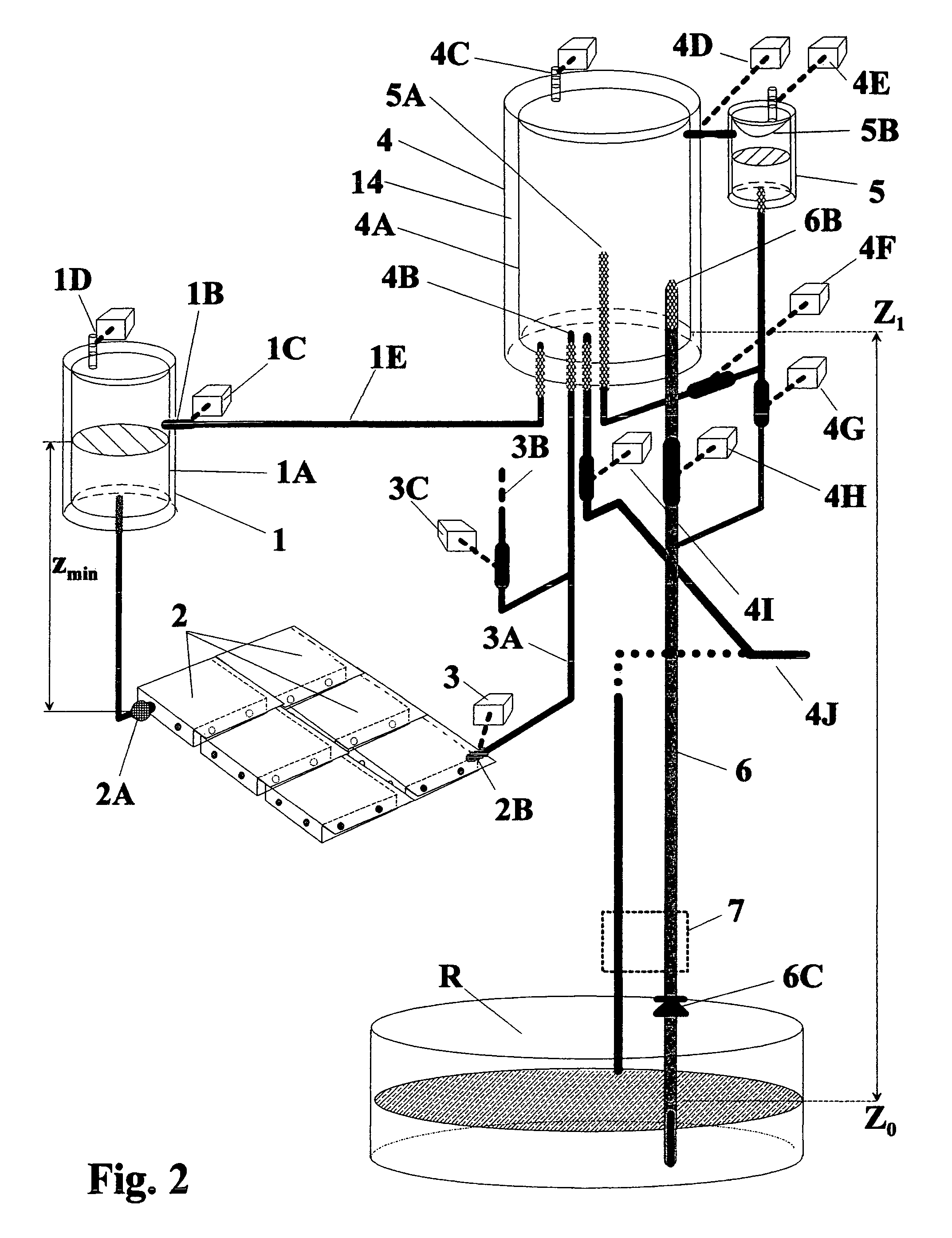
[0002]The present invention relates to fluid displacement systems adapted to be driven by solar energy. In particular, the present invention relates to various fluid displacement devices (e.g., pumps) that utilize solar energy to, for example, displace a controlled volume of fluid from a lower elevation to a higher elevation.
[0003]2. Description of Related Art
[0004]In many regions of the world (e.g., Africa and Middle East), consumable water resource is very much limited. On the other hand, these region typically enjoys an abundance of solar energy. Therefore, it would be highly beneficial to be able to use the solar energy to pump water from underground, to transport water from nearby stream or river, or to generate electricity.
[0005]Unfortunately, however, possibility of utilizing the solar energy as a useable source of energy has been widely ignored in many of these regions because, at least in part, most of the devices for converting solar energy t...
PUM
 Abstract
Description
Claims
Application Information