
Wavelength division multiplexing module

Inactive Publication Date: 2011-02-08
COMMSCOPE TECH LLC
View PDF70 Cites 68 Cited by
  • Summary
  • Abstract
  • Description
  • Claims
  • Application Information

AI Technical Summary

Benefits of technology

[0010]The present invention relates to a telecommunications assembly including a chassis and a plurality of modules mounted within the chassis. Within an interior of each of the modules is located a fiber optic component. In one embodiment, the fiber optic component may be a fiber optic splitter. In another embodiment, the fiber optic component may be a fiber optic division multiplexer / demultiplexer. The modules may include one or more signal input locations at the rear of the module housing or at the front of the module housing adjacent signal output locations. In the case of a multiplexer / demultiplexer, the signal input locations also act as signal output locations since the module may be configured to both demultiplex signals coming in and multiplex signals going out of the module. When the module is used as a fiber optic division multiplexer / demultiplexer module, the multiplexer / demultiplexer, as a receiver, is configured to demultiplex multiple optical carrier signals carried by the single input optical fiber into different wavelengths of laserlight as customer output signals. As a transmitter, the multiplexer / demultiplexer is configured to multiplex the customer signals, which are different wavelengths of laserlight, and combine them into a single optical fiber to be outputted from the module.

Problems solved by technology

While the chassis may accept several modules, the initial installation may only include fewer modules mounted in the chassis, or enough to serve current needs.
These chassis may be configured with limited access to one or more sides, or may be mounted in cramped locations.

Method used


Image

  • Wavelength division multiplexing module
  • Wavelength division multiplexing module
  • Wavelength division multiplexing module

Examples


Embodiment Construction

[0079]Reference will now be made in detail to exemplary aspects of the present invention which are illustrated in the accompanying drawings. Wherever possible, the same reference numbers will be used throughout the drawings to refer to the same or similar parts.

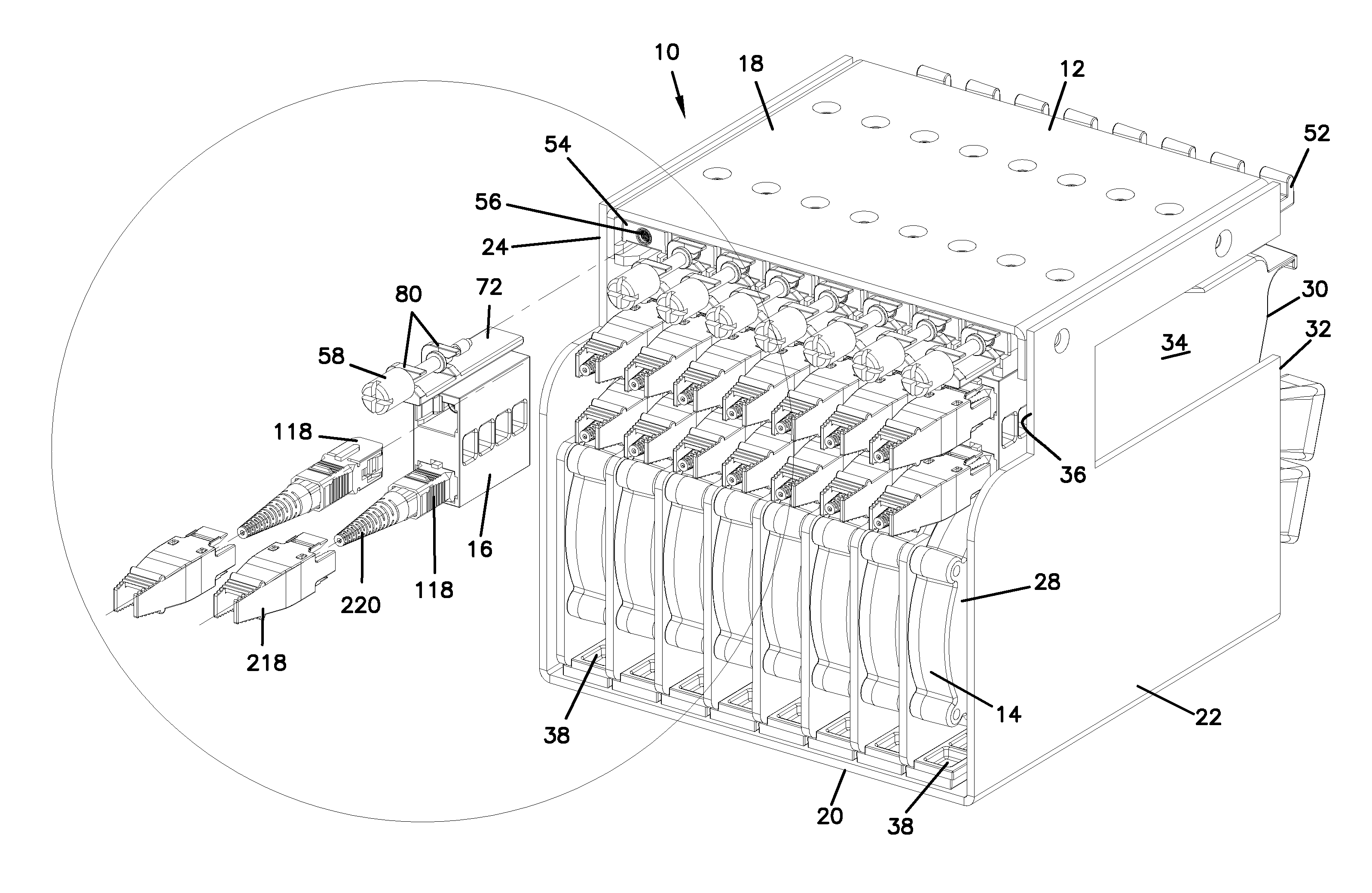
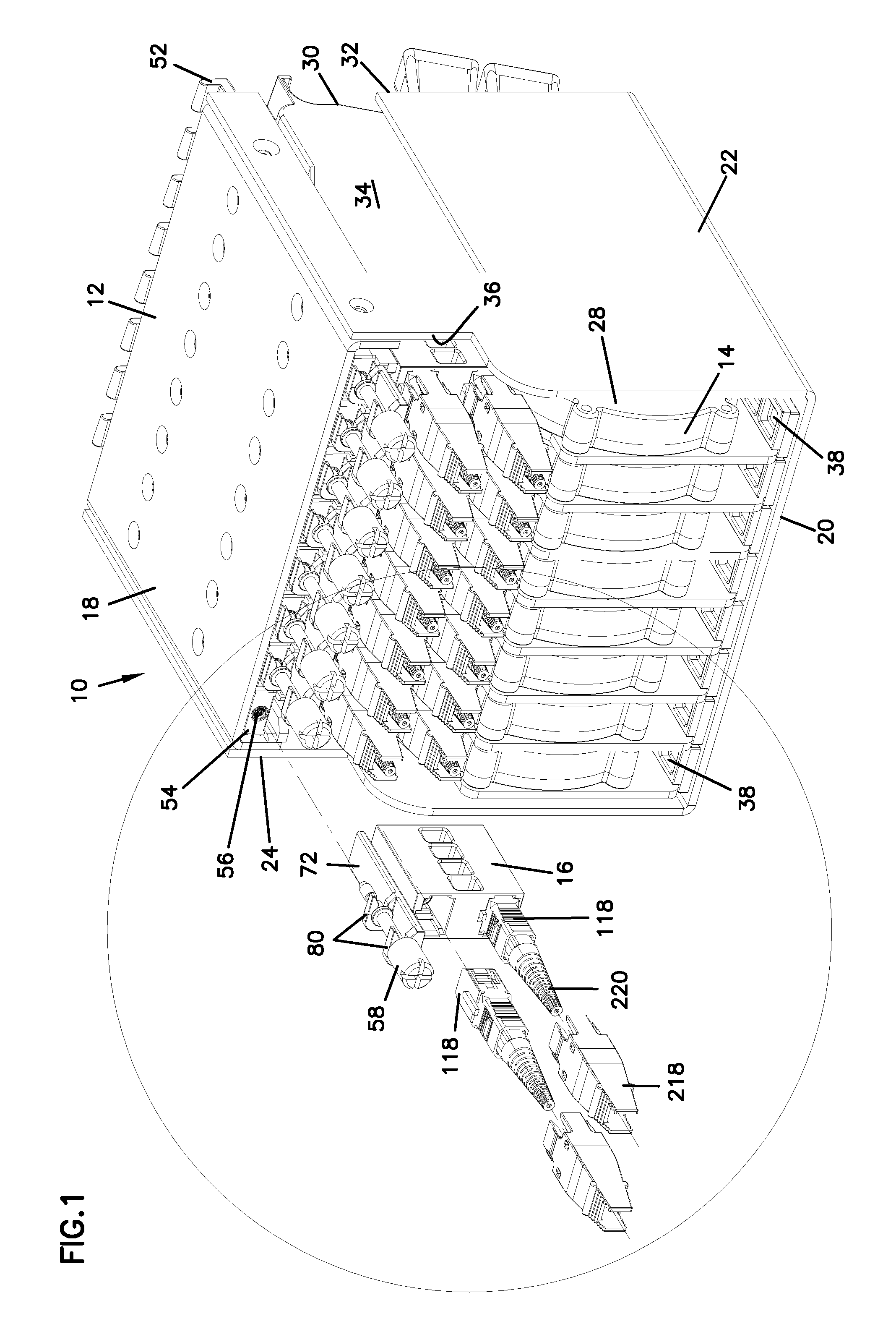
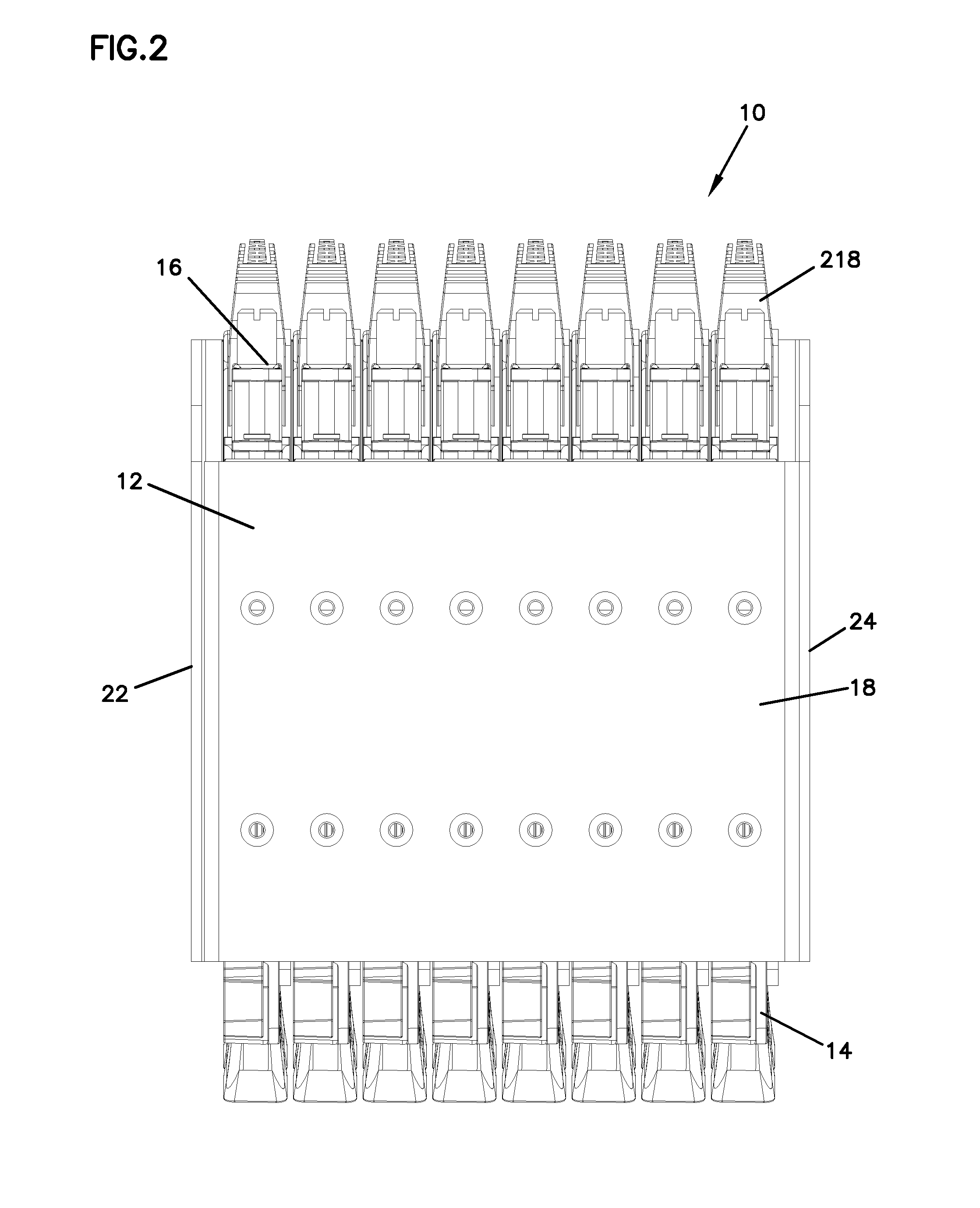
[0080]FIGS. 1-7 illustrate a telecommunications assembly 10 that includes a telecommunications chassis 12 and a plurality of fiber optic splitter modules 14 adapted to be mounted within chassis 12. Fiber optic splitter modules 14 are configured to be slidably inserted within chassis 12 and be optically coupled to adapter assemblies 16 mounted within chassis 12. Adapter assemblies 16 mounted within chassis 12 form connection locations between connectors terminated to an incoming fiber optic cable and connectors of splitter modules 14 as will be discussed in further detail below.

[0081]Still referring to FIGS. 1-7, chassis 12 includes a top wall 18 and a bottom wall 20 extending between a pair of opposing transverse sidewalls, 2...


PUM


Abstract

A telecommunications module includes a main housing portion and a cover, the main housing portion defining a first sidewall, a front wall, a rear wall, a top wall, and a bottom wall, the cover defining a second sidewall when mounted on the main housing portion. An optical component located within the module receives an input signal from a signal input location of the housing and outputs an output signal toward a signal output location on the front wall. The telecommunications module is configured such that the signal input location can be selected to be either on the front wall or the rear wall of the main housing. The cover defines a protrusion extending from the second sidewall toward the main housing portion, the protrusion being selectively breakable to expose a recess on the front wall of the main housing portion that defines a signal input location.

Description

CROSS REFERENCE TO RELATED APPLICATION(S)[0001]This application is a continuation-in-part of application Ser. No. 11 / 975,905, filed Oct. 22, 2007, which application is incorporated herein by reference.FIELD[0002]The present disclosure generally relates to fiber optic telecommunications equipment. More specifically, the present disclosure relates to fiber optic modules and chassis for holding fiber optic modules.BACKGROUND[0003]In fiber optic telecommunications systems, it is common for optical fibers of transmission cables to be split into multiple strands, either by optical splitting of a signal carried by a single stranded cable or by fanning out the individual fibers of a multi-strand cable. Further, when such systems are installed, it is known to provide excess capacity in the installations to support future growth and utilization of the fibers. Often in these installations, modules including splitters or fanouts are used to provide the connection between transmission fibers and...

Claims


Application Information

Patent Timeline
Patent Type & Authority Patents(United States)
IPC IPC(8): G02B6/00
CPCG02B6/444G02B6/4471G02B6/4453G02B6/4444G02B6/44528G02B6/44526G02B6/44715G02B6/29382G02B6/3897G02B6/4452G02B6/4457G02B6/4472G02B6/2938G02B6/4446
Inventor ZIMMEL, STEVEN C.
Owner COMMSCOPE TECH LLC
Features
  • Generate Ideas
  • Intellectual Property
  • Life Sciences
  • Materials
  • Tech Scout
  • Unparalleled Data Quality
  • Higher Quality Content
  • 60% Fewer Hallucinations
Learn More