Real-time global optimization of building setpoints and sequence of operation

a global optimization and building technology, applied in the direction of electrical programme control, program control, instruments, etc., can solve the problems of not fully addressing and solving the need for optimization and efficiency in today's market, and not the best device by which to effectuate optimization of efficiency, so as to achieve the effect of convenient us

Active Publication Date: 2011-02-22
SLOUP CHARLES J +2
View PDF45 Cites 154 Cited by
  • Summary
  • Abstract
  • Description
  • Claims
  • Application Information

AI Technical Summary

Benefits of technology

[0021]The present invention provides a building heating / cooling system energy optimization method for a building having at least one air handling unit (AHU) and a heating / cooling system including at least a condenser unit, a heat transfer unit and a cooling unit operative to circulate water for heating and cooling of the building, the method including the steps of providing a mathematical model of the heating / cooling system including at least the efficiency profile of the components of the heating / cooling system and obtaining real-time weather information including at least outside temperature and outside humidity. The next step would involve the reading of the input water temperature (IWT) of the heating / cooling system prior to adjustment of the water temperature, the output water temperature (OWT) after adjustment of the water temperature by the heating / cooling system, the supply air temperature (SA) output to the building via the at least one air handling unit and the ambient air temperature (AA) within the building and transferring the real-time weather information, the IWT, the OWT, the SA and the AA, collectively the real-time data, to an optimization system, the optimization system operative to analyze the real-time data in coordination with the mathematical model by assigning at least three selected values in a range surrounding and including the current values of each of the IWT, the OWT and the SA for each of the IWT, the OWT and the SA and calculating the efficiency profile of the components of the heating / cooling system for each of the at least three selected values for each of the IWT, the OWT and the SA. The values calculated to provide the highest efficiency profile of the components of the heating / cooling system would then be selected by cooperatively optimizing each of the IWT, the OWT and the SA and the IWT, the OWT and the SA would be periodically reset to the values selected by the optimization system to generally maximize the efficiency profile of the components of the heating / cooling system.
[0022]The present invention as thus described has many advantages over those devices found in the prior art. The primary difference from the prior art and the present invention rests in the dependency of the setpoints on the other building mechanical loops. A primary goal of this invention is to allow each mechanical loop to perform with the best combined operational scheme with all three loops under consideration in real-time, namely the supply air temperature, input water temperature and the output water temperature, which in the cooling mode would be the supply air temperature, chilled water temperature and condenser water temperature. This will reduce the chance for different control loops to fight against one another, improving on the significant shortcomings of the prior art. Also, the optimization system of the present invention is designed to focus virtually solely on the optimization of energy usage without sacrificing space temperature criteria, namely the room setpoint, which is the only variable directly set by the space occupant, and therefore room setpoint is not one of the monitored control loops. Of course, however, sequences which allow room setpoint changes are certainly compatible with this system but do not comprise significant portions of the present invention. Finally, the combination of features found on the present invention render the invention far more effective and easy to use than those devices found in the prior art. Therefore, the present invention provides a substantial improvement over those methods and control systems found in the prior art.

Problems solved by technology

Building owners react to increasing utility costs by demanding better designs from engineering professionals yet standard practice has inherent limitations to the overall benefit that can be provided building owners.
While this allowed for a generic or “one size fits all” approach, there are inherent problems in this approach which do not fully address and solve the need for optimization and efficiency demanded in today's market.
For example, the prior art approach described above will often result in control loops acting against one another, as the independent optimization of the control loops commands, as when the optimization system resets the chilled water temperature to reduce chiller energy consumption without recognizing the impact on the air handler unit (AHU).
Therefore, it is not the best device by which to effectuate optimization of efficiency, and therefore is best not included as one of the interactive loops in an optimization system.
While this allowed for self-contained programming, there are inherent problems such as the computing load placed on building automation controllers, the difficulty of executing intricate predictive programming in control processors and the programming of software made for feedback applications.
Not only do the weather prediction tools have an associated inaccuracy but there are also questions regarding the correlation of a “local” forecast with the actual site conditions impacting variables.
And, last but not least, these applications were limited to only considering the optimization of the plant without extending the analysis to consider the impact of the AHU on the total energy balance as well as any system-limiting factors generated by the air terminal units typically found in most AHU systems.

Method used


Image

  • Real-time global optimization of building setpoints and sequence of operation
  • Real-time global optimization of building setpoints and sequence of operation
  • Real-time global optimization of building setpoints and sequence of operation

Examples


Embodiment Construction

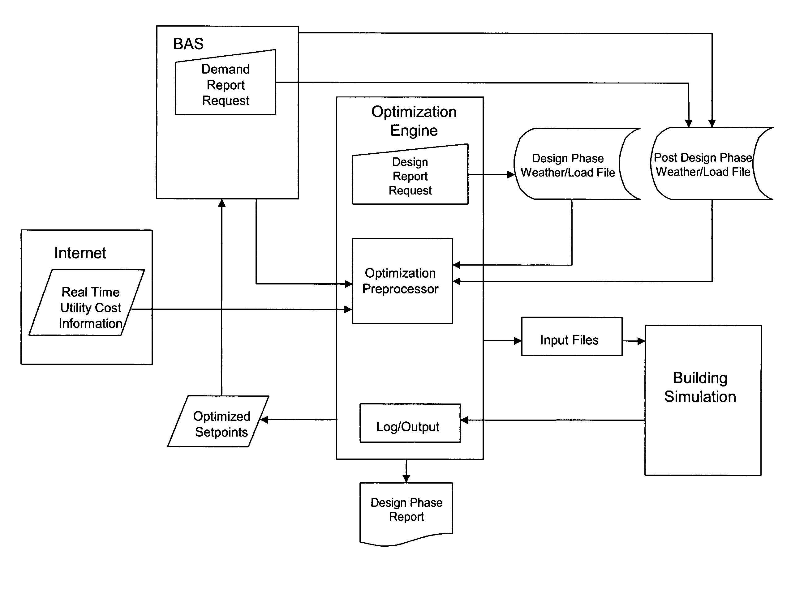
[0027]The improved optimization configuration of the present invention is best shown in FIG. 5 as including a building automation system, energy simulation software and an optimization engine working in concert with one another.

[0028]In order to address the need for an integrated / comprehensive view of building energy consumption, this configuration solves the optimization of interactive loops simultaneously to ensure the control loops are working in concert with one another while reducing localized minimums and maintaining maximum accuracy. It should be noted, however, that in especially large facilities, there may be the need to solve multiple global problems in several smaller parts and sum the results and while this may speed up the calculations it may also add inaccuracy to the result, and therefore it is preferred that the following description of the preferred method of the present invention be applied whenever possible.

Building Automation System (BAS)

[0029]1. General Descript...


PUM


Abstract

A building heating / cooling system energy optimization method for a building having a heating / cooling system includes the steps of providing a mathematical model of the heating / cooling system, obtaining real-time weather information, reading the input water temperature (IWT), the output water temperature (OWT) and the supply air temperature (SA) output to the building, periodically transferring the IWT, the OWT and the SA to an optimization system which is operative to analyze the real-time data in coordination with the mathematical model by assigning at least three selected values in a range surrounding and including the current values of each of the IWT, the OWT and the SA and calculating the efficiency profile of the components of the heating / cooling system for each of the selected values, then cooperatively optimizing and selecting those values calculated to provide the highest efficiency profile, then periodically resetting the system values to those selected by the optimization system.

Description

BACKGROUND OF THE INVENTION[0001]1. Technical Field[0002]The present invention is directed to the optimization of building energy use and, more particularly, to an improved optimization configuration whereby the building automation system, an energy simulation software package and an optimization engine work in concert with one another to examine variables relating to operational and environmental temperature values and cooperatively optimize those variables to generate setpoints for the building systems to reduce the building HVAC system's operational costs and increase the operating efficiency of the heating / cooling system of the building.[0003]2. Description of the Prior Art[0004]The need for more efficient and sustainable buildings has grown as the number of buildings being built and renovated continues to rise in the presence of sharply rising energy costs. Building owners react to increasing utility costs by demanding better designs from engineering professionals yet standard ...

Claims


Application Information

Patent Timeline
Patent Type & Authority Patents(United States)
IPC IPC(8): G05B19/04G05D23/19G21C7/36F25B29/00G05B19/18
CPCG05B13/041G05B17/02
Inventor SLOUP, CHARLES J.KARNES, DANIELHENZE, GREGOR P.
Owner SLOUP CHARLES J
Why Eureka
Try Eureka