Sealing device

a sealing device and a technology of a sealing device, applied in the direction of fluid removal, earthwork drilling and mining, borehole/well accessories, etc., can solve the problems of unreliable method, glass shattered into tiny particles, and fluids leaking out of the well during operation

Active Publication Date: 2011-03-22
BJRGUM MEKANISKE
View PDF4 Cites 71 Cited by
  • Summary
  • Abstract
  • Description
  • Claims
  • Application Information

AI Technical Summary

Benefits of technology

[0029]One advantage of the present invention is that the plug device according to the present invention can be decomposed in a controlled manner, with the result that the exact time can be determined for when free through-flow in the well can be expected to occur, without the use of explosives.
[0030]The invention will now be described in more detail with reference to the following figures, in which:
[0031]FIG. 1a is a cross section of the plug device in a closed position according to the present invention.
[0032]FIG. 1b is an enlarged view of a section of the plug device according to FIG. 1a.
[0033]FIG. 2a is a cross section of the plug device in an open position according to the present invention.
[0034]FIG. 2b is an enlarged view of a section of the plug device according to FIG. 2a.

Problems solved by technology

If such a check is not carried out, there is a risk of fluids leaking out of the well during operation.
The glass used in known plugs has undergone a hardening treatment, with the result that it is brittle on one side and on the other side it possesses the strength to resist the severe pressure stresses to which it is exposed.
In today's systems, a plug like that mentioned above is removed by means of an explosive charge, with the result that the glass is shattered into tiny particles, which are easily washed out of the well without leaving any potentially harmful residue.
During operations from floating rigs, however, this method will be too slow and unreliable, in light of the operating costs for this kind of platform.
In this case it will be impossible to predict the exact time when the plug is removed and the passage through the well opens.

Method used


Image

  • Sealing device
  • Sealing device
  • Sealing device

Examples


Embodiment Construction

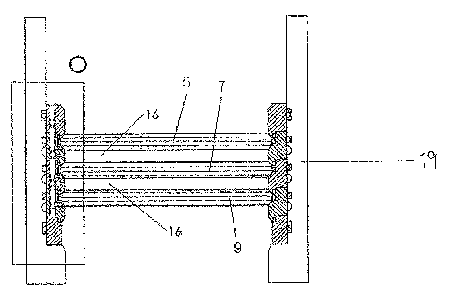
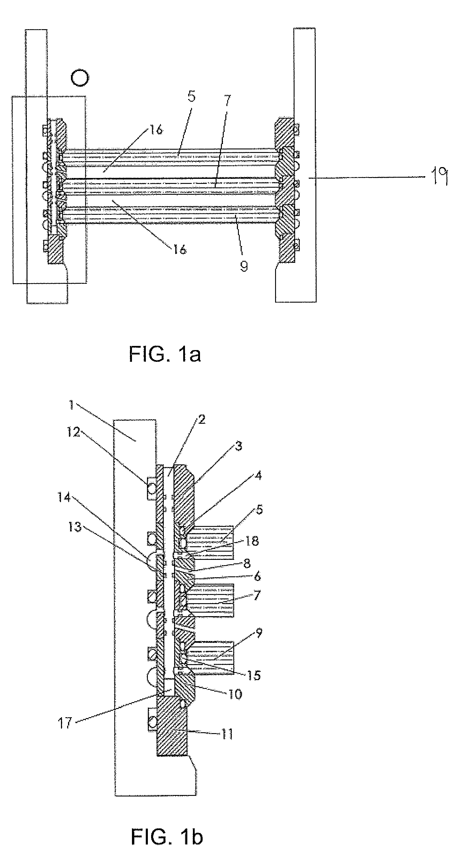
[0035]FIGS. 1a and 1b illustrate a cross section of the plug device according to the invention. The actual plug is mounted in a housing 1, which is a precise fit for the said plug. The plug comprises a number of strata, comprising layered division of material strata, such as glass, ceramics and the like, plus a number of cavities arranged between the said material strata. In the figure a plug device is illustrated comprising three material strata 5, 7 and 9 and two intermediate cavities 16, but it should be understood that the invention is not limited to this, but that a plug device is only described with a limited number of material strata in order to enhance the understanding of the invention's function. The invention can easily be modified to include additional material strata according to requirements, and is therefore not further described herein.

[0036]In the further description the material stratum is called a glass stratum, even though the invention is not limited thereto, bu...


PUM


Abstract

A decomposable sealing device is described for use in liquid-filled pipes or boreholes, which is characterised in that the sealing device comprises a sleeve-shaped element (19) which envelops a number of strata (5, 7, 9) completely or partly in the pipe's radial and a longitudinal direction, comprising layered division of a number of decomposable strata (5, 7, 9) and a number of closed liquid-filled chambers (16) arranged between the strata (5, 7, 9) and where the sleeve-shaped element (19) comprises a body (2) which can be rearranged to establish connection between the respective chambers (16) and one or more grooves (14) in the inner wall of a pipe. A method for decomposing the sealing device is also described.

Description

BACKGROUND OF THE INVENTION[0001]1. Field of the Invention[0002]The present invention relates to a decomposable sealing device for use in pipes or boreholes, as well as a method related thereto.[0003]2. Description of Related Art[0004]It is well known within the oil industry that production wells have to be tested before being put into service. One of these tests involves checking whether the well can withstand the pressure at which it is to be operated during oil / gas production. If such a check is not carried out, there is a risk of fluids leaking out of the well during operation.[0005]In order to conduct such tests, a plug device is placed down in the well to shut off the passage. A pressure is applied from the surface by means of a suitable fluid, and by checking the well over a period of time, it is possible to investigate whether the well is sufficiently leak-proof. The plug is normally mounted as a lower part of a production tubing, and lowered internally in a casing which is ...

Claims


Application Information

Patent Timeline
Patent Type & Authority Patents(United States)
IPC IPC(8): E21B33/12E21B33/13
CPCE21B33/1208E21B33/134E21B34/063E21B47/1025E21B47/117
Inventor BJORGUM, STIG OVE
Owner BJRGUM MEKANISKE
Why Eureka
Try Eureka