Clamping apparatus

a clamping and non-power technology, applied in the direction of clamps, manufacturing tools, etc., can solve problems such as difficulty in us

Inactive Publication Date: 2011-03-22
HILL THOMAS C
View PDF8 Cites 8 Cited by
  • Summary
  • Abstract
  • Description
  • Claims
  • Application Information

AI Technical Summary

Problems solved by technology

Even then, there is a high probability that the boards will be bowed after the clamping process which makes them difficult to use in subsequent operations and in many cases, they must be scrapped.

Method used


Image

  • Clamping apparatus
  • Clamping apparatus
  • Clamping apparatus

Examples


Embodiment Construction

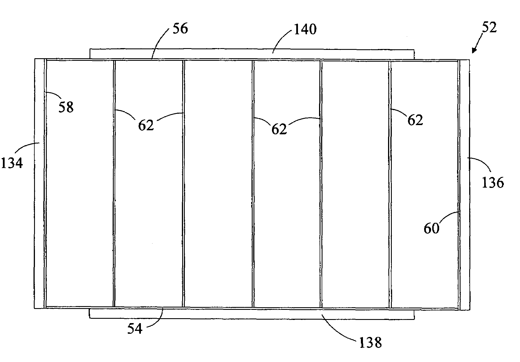
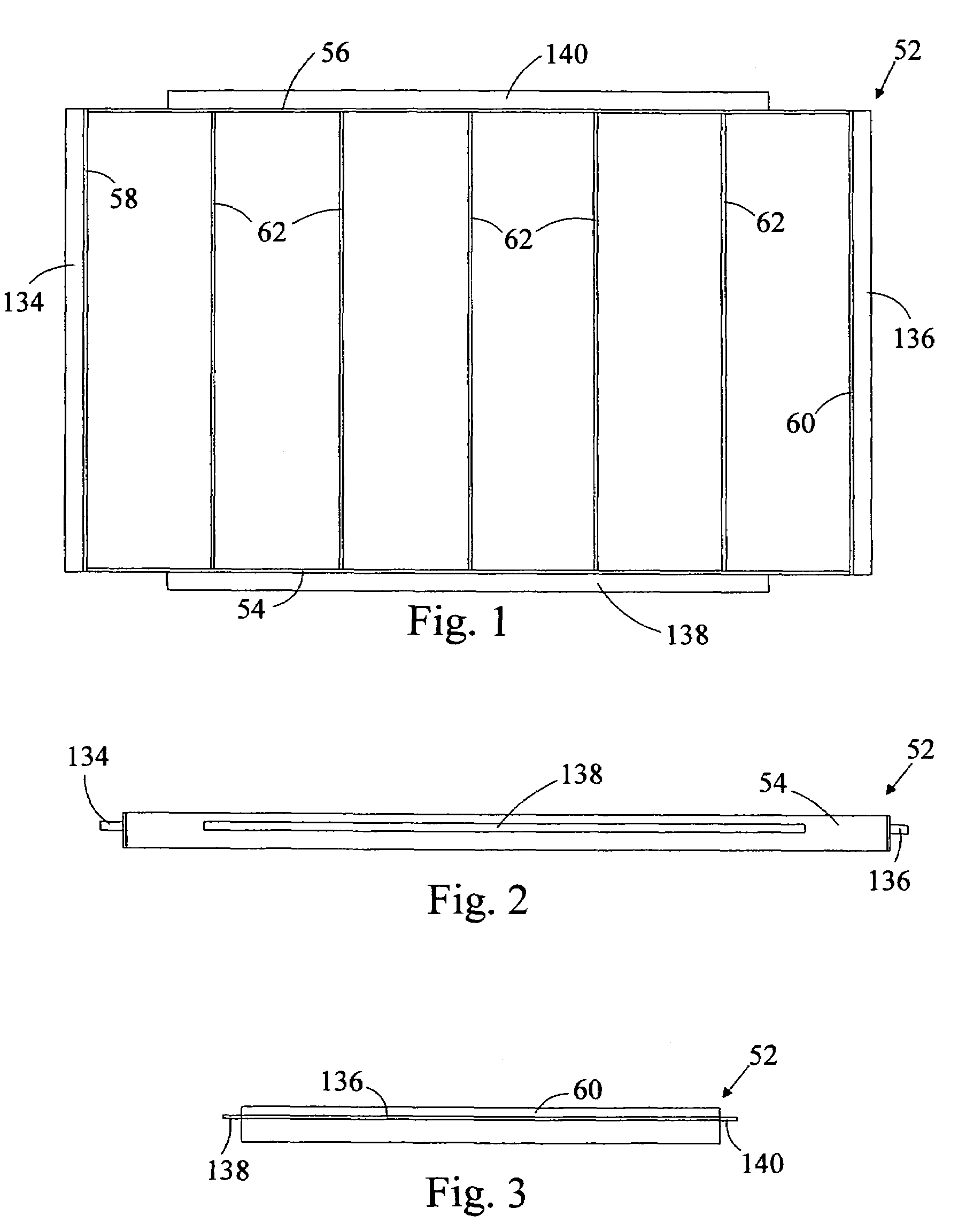
[0022]Like reference characters refer to like parts throughout the several figures of the clamping apparatus. FIG. 1 is a top view of the top section 52 which is rectangular in shape. It has a front side 54, a back side 56, a left side 58, a right side 60, and crosswalls 62 that extend from the front side 54 to the back side 56 and are substantially parallel to the left side 58 and the right side 60. There is a clamping bar 134 on the left side 58 and a clamping bar 136 on the right side 60. There is a clamping bar 138 attached to the front side 54 and a clamping bar 140 attached to the back side 56 of the top section 52. FIG. 2 is a front view of the top section 52 with the clamping bar 134 on the left side 58 and the clamping bar 136 on the right side 60 and the clamping bar 138 on the frontside 54. The front side 54 is rectangular in shape. The bottom edge of the crosswalls 62 and the bottom edge of the front side 54, backside 56, left side 58, and right side 60 of the top sectio...


PUM


Abstract

A non-power operated clamping apparatus is disclosed which is made up of a top section, middle section, and bottom section. There are first direction clamps located on the left side and right side of the middle section and the bottom section is positioned within the first direction clamps and the sides of the middle section. There are second direction clamps between the bottom section and middle section and between the top section and middle section. The workpiece, comprising members of wood glued edge-to-edge, is placed between the top section and middle section and subjected to a first direction compressive force and a second direction compressive force perpendicular to the first direction compressive force.

Description

FIELD OF THE INVENTION[0001]The present invention is a non-power operated clamping apparatus that can be used to clamp a plurality of wood pieces using two perpendicular compressive forces.BACKGROUND OF THE INVENTION[0002]Wood panels can be constructed by gluing a number of boards, edge-to-edge, to form a flat panel. Pipe clamps or other types of clamps are typically used to squeeze the boards together. The clamps are placed on both sides of the boards to reduce bowing. Even then, there is a high probability that the boards will be bowed after the clamping process which makes them difficult to use in subsequent operations and in many cases, they must be scrapped. A wood panel made with boards glued edge-to-edge needs to be flat for subsequent operations.SUMMARY OF THE INVENTION[0003]The present invention is a clamping apparatus that clamps boards to make a flat panel. It is a non-power operated clamping apparatus which is made up of a top section, middle section, and bottom section....

Claims


Application Information

Patent Timeline
Patent Type & Authority Patents(United States)
IPC IPC(8): B25B5/14
CPCB25B5/145
Inventor HILL, THOMAS C.
Owner HILL THOMAS C
Why Eureka
Try Eureka