Compensation for display device flicker

a display device and compensation technology, applied in the field of images, can solve the problems of significant flickering of the luminance flash or luminance jump the inability to adjust the brightness of the display device, so as to reduce the luminance flash, minimize the average luminance variation across the transition and display data frame, and maintain the effect of average luminan

Active Publication Date: 2011-05-31
DRS LAUREL TECH PARTNERSHIP D B A DRS LAUREL TECH
View PDF47 Cites 13 Cited by
  • Summary
  • Abstract
  • Description
  • Claims
  • Application Information

AI Technical Summary

Benefits of technology

[0010]In one or more embodiments, an algorithm is presented that inserts transition frames in between display data frames, such that the average luminance variation across transition and display data frames is minimized (e.g., such that a substantially constant average luminance is perceived by a user), substantially reducing the luminance flash resulting from differing state transition rates (e.g., color state transition rates) between display data frames. In one or more embodiments, the algorithm processes display data frames at a rate of up to the refresh rate of the display device, and creates transition frames (e.g., where the color state transition rates are slowed) to adjust the average luminance. In one or more embodiments, the result of the algorithm is a sequence of dark and light luminance flashes that effectively cancel each other creating the perception to a user of substantial flicker reduction.
[0011]Further, in one or more embodiments, the algorithm allows for operator adjustment of flicker reduction accomplished with the inserted transition frames. Yet further, in one or more embodiments, the algorithm with operator adjustment allows the operator to compensate for initial and final color state (image content), manufacturing process variation, temperature variation, individual human eye sensitivity variations and manufacturer design variation (any LCD display).
[0018]Another method for use in correcting flicker of a display according to another embodiment of the present invention includes providing a plurality of display data frames to be sequentially displayed using the plurality of pixel elements of the display and inserting at least one transition data frame between each display data frame and a subsequent display data frame of the plurality of the display data frames (e.g., the at least one transition data frame being generated using one or more user provided parameters). Further, the method includes providing an input apparatus to a user for modifying the one or more user provided parameters used to generate the at least one transition data frame so as to allow the user to adjust one or more luminance characteristics of the display of the plurality of display data frames using the plurality of pixel elements.

Problems solved by technology

The problem of luminance flashes or luminance jumps on LCDs is caused, at least in part, by differences between the rise and fall rates of pixel luminance changes.
A scrolling image on a display, such as a sonar waterfall image, may exhibit substantial flicker with each scroll step of the image.
Differing rise and fall rates during these complementary pixel transitions may result in discernible but unexpected and undesirable transient luminance variations or flashes, also referred to as flicker.
The resulting flicker problem, due at least in part to the differing rise and fall rates, does not seem to affect enough users of LCDs to influence the decision to minimize pixel response time rather than match rise and fall rates.
One drawback of the Gadeyne et al. apparatus and method is that this method is applied to all pixel elements within the LCD display.
By slowing all pixel transition times to the slowest pixel transition time, the Gadeyne et al. method may cause smearing and loss of contrast when pixel changes happen faster than the slowest pixel transition.
Therefore, motion video, such as camera video, played in a separate window on the display would receive potentially undesirable smearing and contrast loss.
Another drawback to the Gadeyne et al. apparatus and method is that a different complex implementation to substantially match the luminance rise and fall times in shape and amplitude is necessary to provide compensation for different specific display devices.
As such, flicker compensated display of a sonar waterfall, for example, is limited only to those devices for which a specific complex implementation has been provided.

Method used


Image

  • Compensation for display device flicker
  • Compensation for display device flicker
  • Compensation for display device flicker

Examples


Embodiment Construction

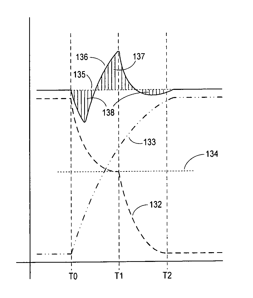
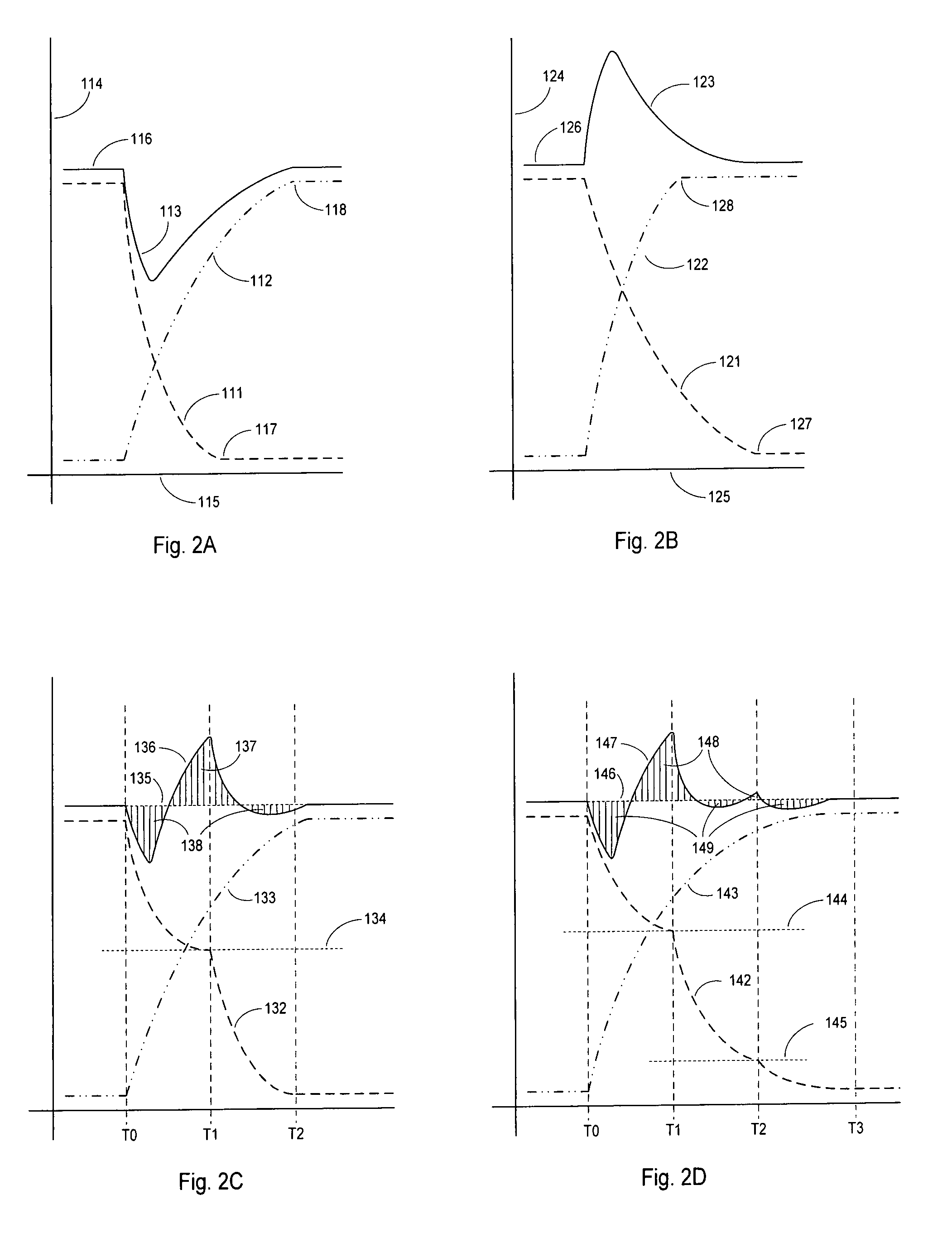
[0040]The present invention shall generally be described with reference to FIGS. 1, 2A-2C, and 3A. Further, various embodiments of the present invention shall then be described with reference to FIGS. 1-4.

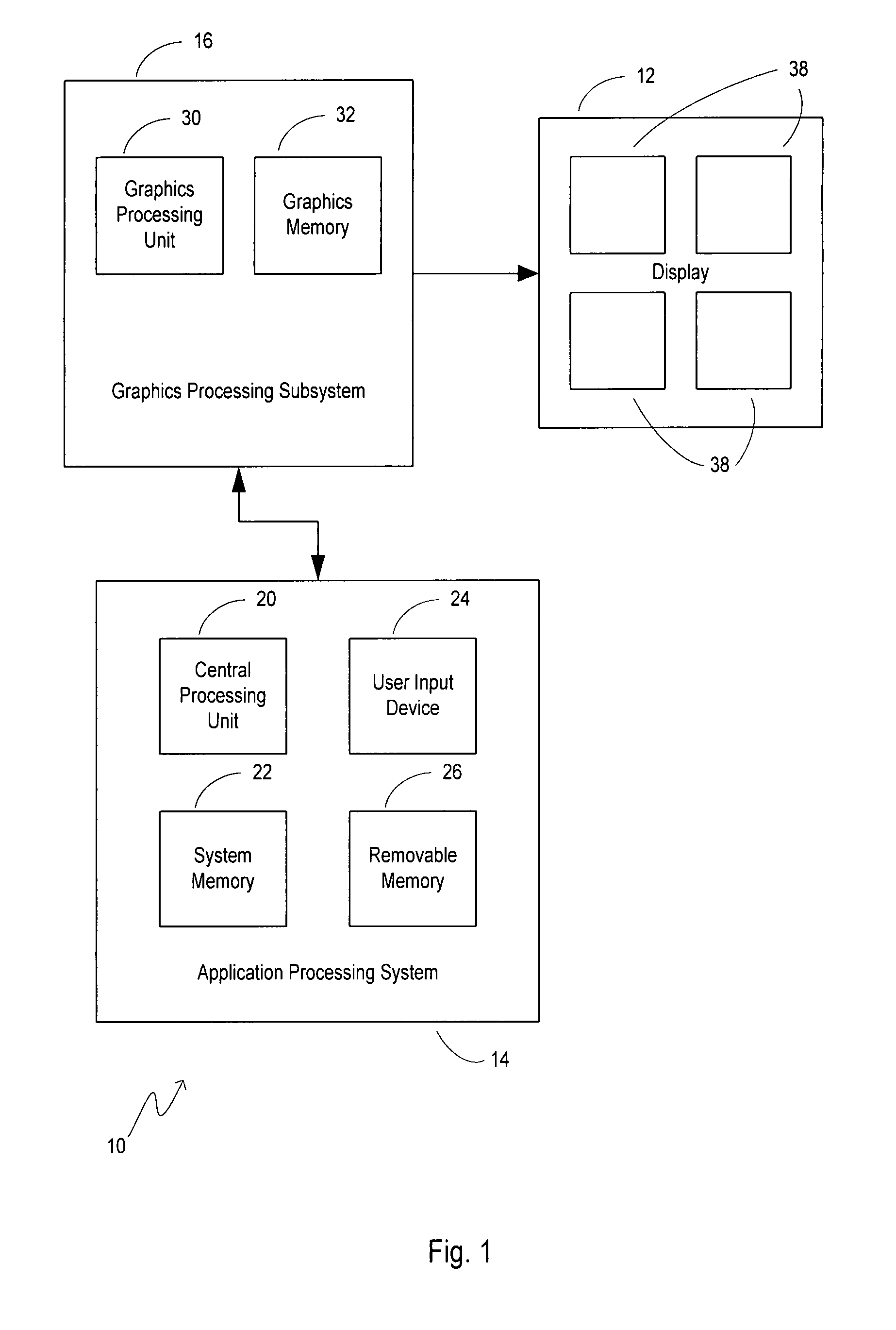
[0041]FIG. 1 shows a general block diagram of a system 10 for correction of flicker on a display device 12 thereof according to one or more embodiments of the present invention. In one embodiment, as shown in FIG. 1, the system 10 includes application processing system 14 associated with graphics processing subsystem 16 (e.g., generally coupled together via a system bus). Generally, the application processing system 14 and graphics processing subsystem 16 are functional to provide a plurality of sequential display data frames.

[0042]As shown in the embodiment of FIG. 1, the application processing system 14 includes a central processing unit (CPU) 20 and a system memory 22 communicating therewith. User input (e.g., selection of user selected parameters to control luminance according ...


PUM


Abstract

Systems and methods are provided for use in correcting flicker of a display (e.g., an LCD display). For example, correction may employ the insertion of at least one transition data frame between display data frames for use in displaying a transition image by pixel elements of the display such that a user perceives display of a constant average luminance by the pixel elements.

Description

CROSS-REFERENCE TO RELATED APPLICATIONS[0001]This application claims the benefit of U.S. Provisional Application Ser. No. 60 / 789,728 filed 6 Apr. 2006, entitled “Compensation for Display Device Flicker,” which is incorporated herein by reference in its entirety.FIELD OF THE INVENTION[0002]The present invention relates generally to the display of images on display devices (e.g., display devices that may have differing state transition rates, such as liquid crystal displays (LCDs)), and, at least in one embodiment, pertains to the display of moving images, for example, from computer data or digital video sources that are displayed on an LCD.BACKGROUND OF THE INVENTION[0003]The display of images on display devices such as a cathode ray tube (CRT) or a liquid crystal display (LCD) is a known art. The problem of luminance flashes or luminance jumps on LCDs is caused, at least in part, by differences between the rise and fall rates of pixel luminance changes. It is also known that the ris...

Claims


Application Information

Patent Timeline
Patent Type & Authority Patents(United States)
IPC IPC(8): G09G3/36
CPCG09G3/3648G09G5/14G09G2320/0247G09G2320/0606G09G2320/0257G09G2320/0261G09G2320/0252
Inventor BENJAMIN, SCOTT JANDRUSIAK, MARTIN J.WERNER, RALPH A.
Owner DRS LAUREL TECH PARTNERSHIP D B A DRS LAUREL TECH
Why Eureka
Try Eureka