Compensation for display device flicker

Active Publication Date: 2007-10-11
DRS LAUREL TECH PARTNERSHIP D B A DRS LAUREL TECH
View PDF27 Cites 40 Cited by
  • Summary
  • Abstract
  • Description
  • Claims
  • Application Information

AI Technical Summary

Benefits of technology

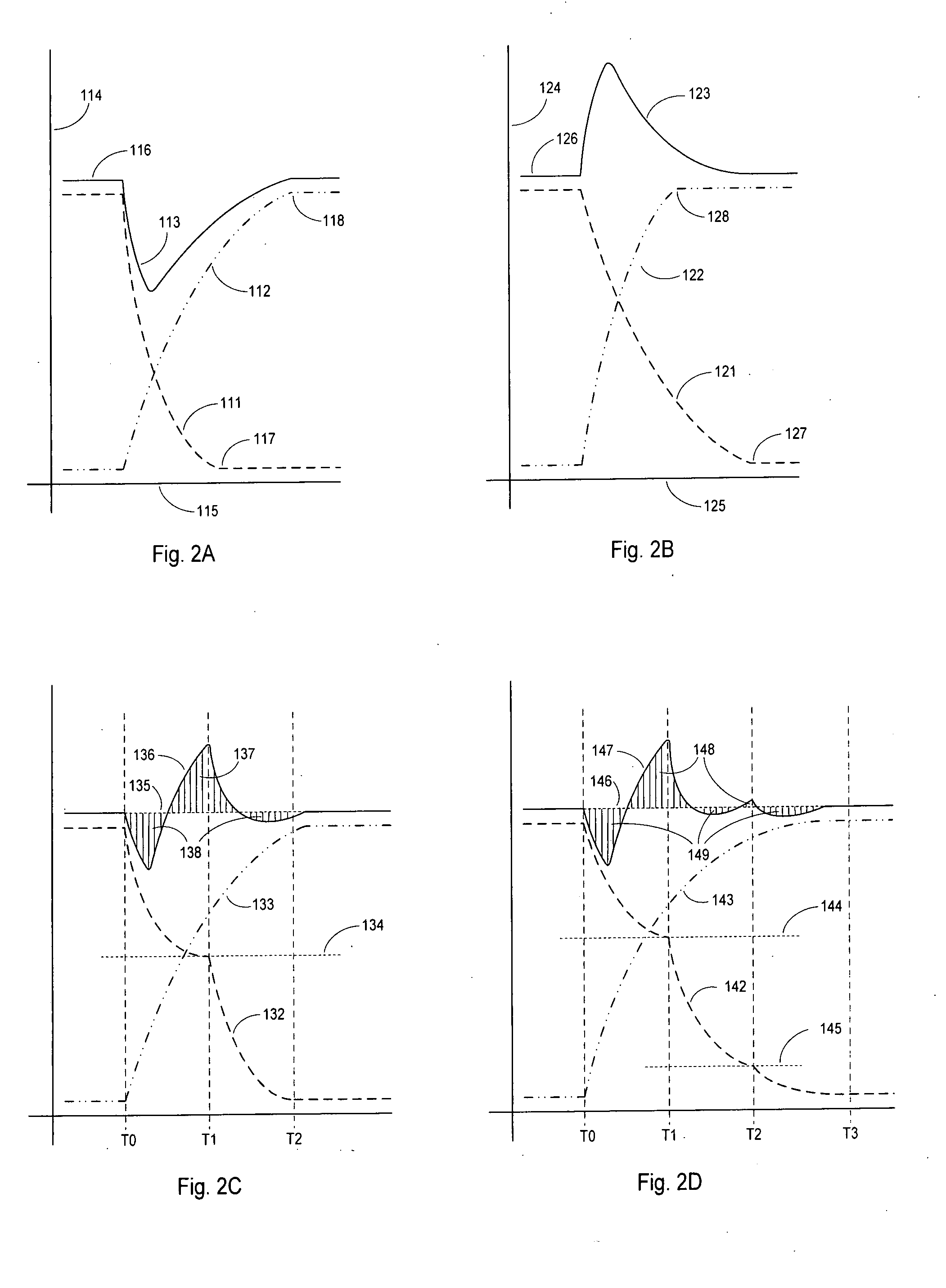
[0009]In one or more embodiments, an algorithm is presented that inserts transition frames in between display data frames, such that the average luminance variation across transition and display data frames is minimized (e.g., such that a substantially constant average luminance is perceived by a user), substantially reducing the luminance flash resulting from differing state transition rates (e.g., color state transition rates) between display data frames.

Problems solved by technology

The problem of luminance flashes or luminance jumps on LCDs is caused, at least in part, by differences between the rise and fall rates of pixel luminance changes.
A scrolling image on a display, such as a sonar waterfall image, may exhibit substantial flicker with each scroll step of the image.
Differing rise and fall rates during these complementary pixel transitions may result in discernible but unexpected and undesirable transient luminance variations or flashes, also referred to as flicker.
The resulting flicker problem, due at least in part to the differing rise and fall rates, does not seem to affect enough users of LCDs to influence the decision to minimize pixel response time rather than match rise and fall rates.
One drawback of the Gadeyne et al. apparatus and method is that this method is applied to all pi

Method used


Image

  • Compensation for display device flicker
  • Compensation for display device flicker
  • Compensation for display device flicker

Examples


Embodiment Construction

[0039]The present invention shall generally be described with reference to FIGS. 1, 2A-2C, and 3A. Further, various embodiments of the present invention shall then be described with reference to FIGS. 1-4.

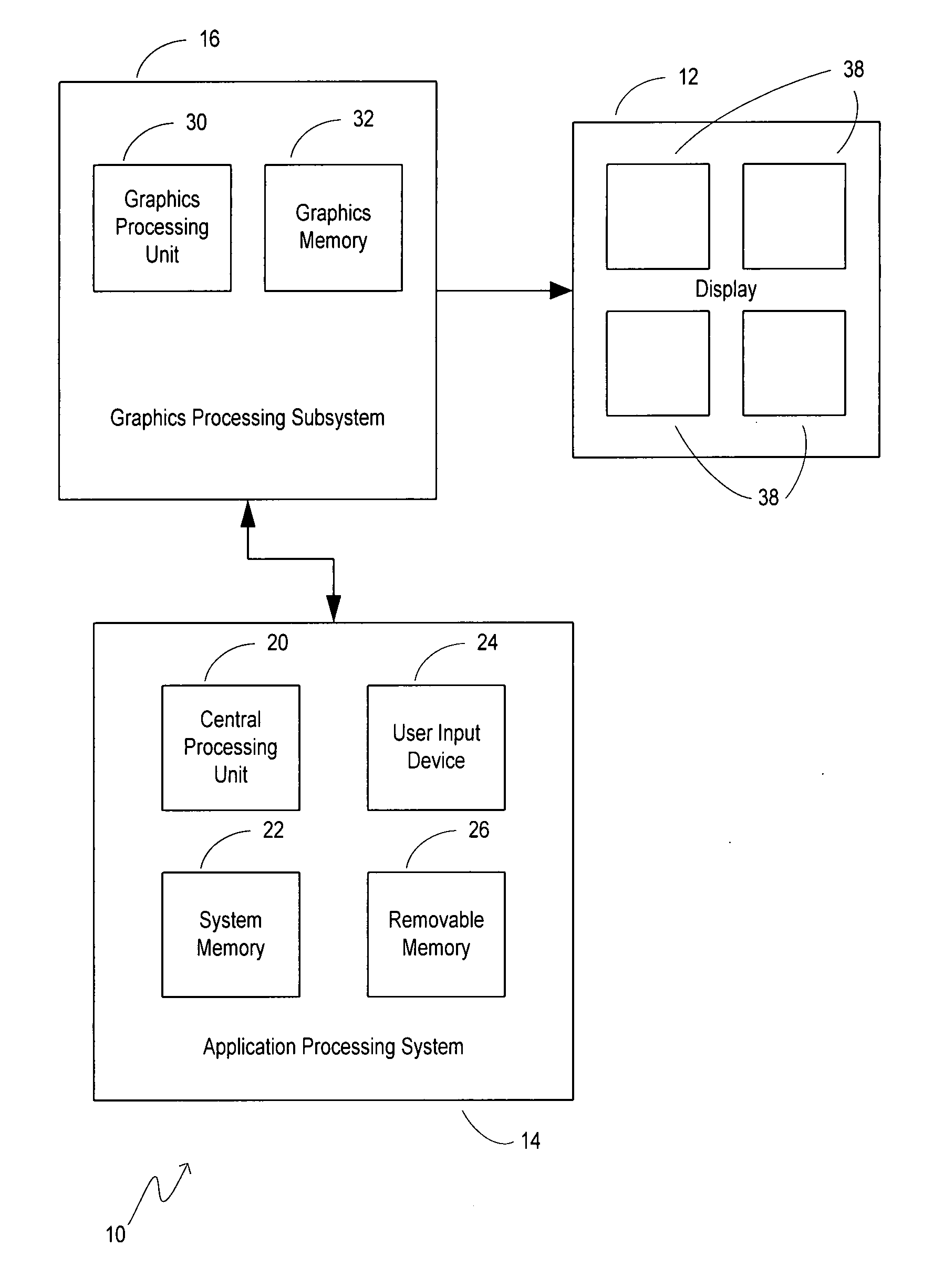
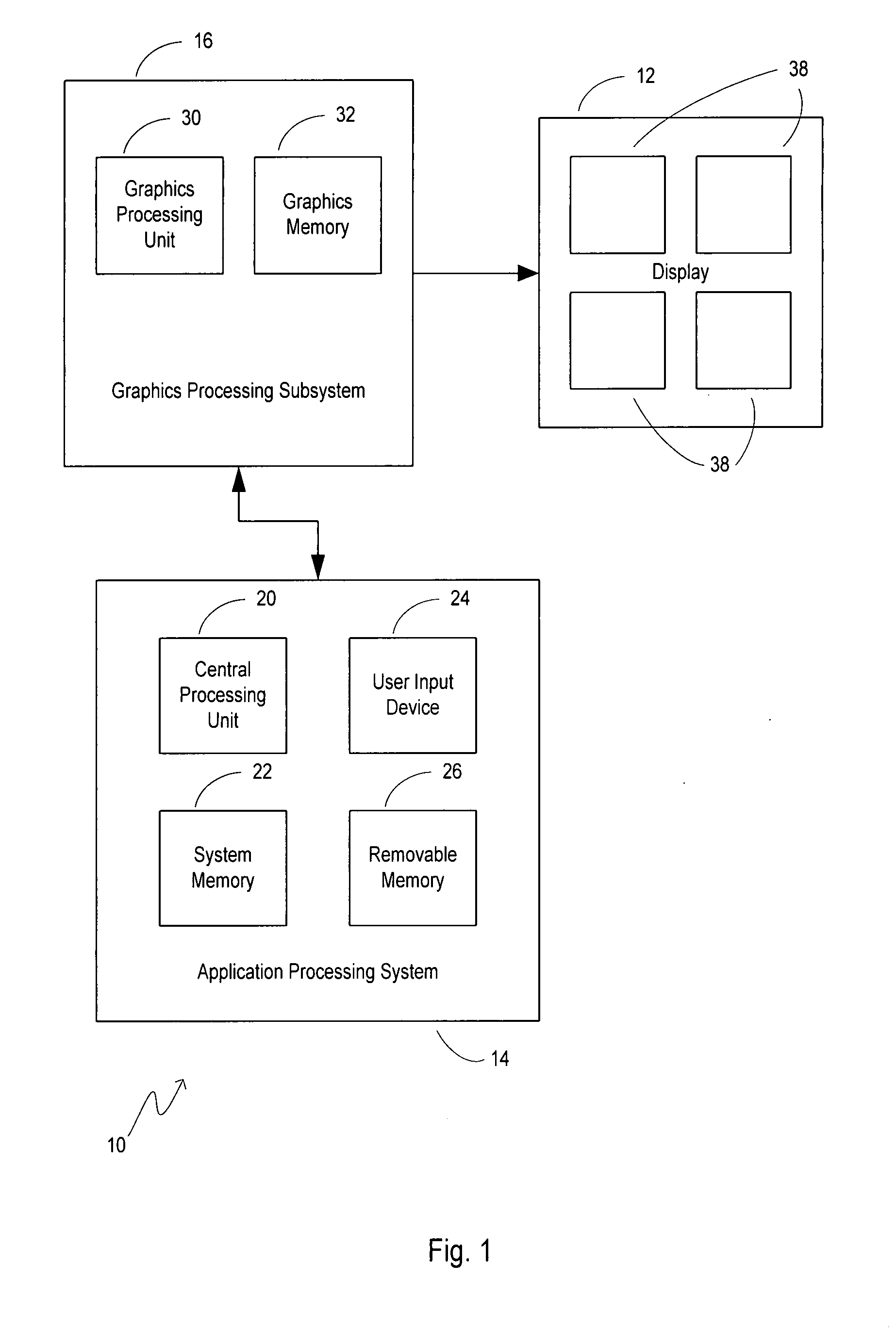
[0040]FIG. 1 shows a general block diagram of a system 10 for correction of flicker on a display device 12 thereof according to one or more embodiments of the present invention. In one embodiment, as shown in FIG. 1, the system 10 includes application processing system 14 associated with graphics processing subsystem 16 (e.g., generally coupled together via a system bus). Generally, the application processing system 14 and graphics processing subsystem 16 are functional to provide a plurality of sequential display data frames.

[0041]As shown in the embodiment of FIG. 1, the application processing system 14 includes a central processing unit (CPU) 20 and a system memory 22 communicating therewith. User input (e.g., selection of user selected parameters to control luminance according ...


PUM


Abstract

Systems and methods are provided for use in correcting flicker of a display (e.g., an LCD display). For example, correction may employ the insertion of at least one transition data frame between display data frames for use in displaying a transition image by pixel elements of the display such that a user perceives display of a constant average luminance by the pixel elements.

Description

CROSS-REFERENCE TO RELATED APPLICATIONS[0001]This application claims the benefit of U.S. Provisional Application Serial No. 60 / 789,728 filed 6 Apr. 2006, entitled “Compensation for Display Device Flicker,” which is incorporated herein by reference in its entirety.FIELD OF THE INVENTION[0002]The present invention relates generally to the display of images on display devices (e.g., display devices that may have differing state transition rates, such as liquid crystal displays (LCDs)), and, at least in one embodiment, pertains to the display of moving images, for example, from computer data or digital video sources that are displayed on an LCD.BACKGROUND OF THE INVENTION[0003]The display of images on display devices such as a cathode ray tube (CRT) or a liquid crystal display (LCD) is a known art. The problem of luminance flashes or luminance jumps on LCDs is caused, at least in part, by differences between the rise and fall rates of pixel luminance changes. It is also known that the r...

Claims


Application Information

Patent Timeline
IPC IPC(8): G09G3/36
CPCG09G3/3648G09G5/14G09G2320/0247G09G2320/0606G09G2320/0257G09G2320/0261G09G2320/0252
Inventor BENJAMIN, SCOTT J.ANDRUSIAK, MARTIN J.WERNER, RALPH A.
Owner DRS LAUREL TECH PARTNERSHIP D B A DRS LAUREL TECH
Why Eureka
Try Eureka