Manually propelled wheelchair device

a wheelchair and motor technology, applied in the field of manual-operated wheelchairs, can solve the problems of not collapsing or not, the muscle power of a single arm cannot be delivered to a single drive wheel of the wheelchair, and the occupant must use both arms, so as to reduce the overall dimension

Inactive Publication Date: 2011-06-14
BIDWELL ALAN +1
View PDF16 Cites 11 Cited by
  • Summary
  • Abstract
  • Description
  • Claims
  • Application Information

AI Technical Summary

Problems solved by technology

A disadvantage associated with one design for conventional two-handed manually-driven wheelchairs is that an occupant must use both arms to manoeuvre the wheelchair at all times. This is most disadvantageous when an occupant needs to carry an object from one point to another, for example from a refrigerator to a kitchen table.
A further disadvantage with known designs of conventional two-handed wheelchairs is due to the fact that, since they have two large rear drive wheels independently connected to the wheelchair frame, the muscle power of a single arm can only be delivered to a single drive wheel of the wheelchair.
One problem associated with single-handed manually-driven wheelchairs is that they are purposely designed for either left or right handed operation, and not both.
A further disadvantage with such prior art single-handed wheelchairs is that they are sometimes not collapsible or do not collapse to a sufficiently compact state, due to the rigid or semi-collapsible drive axle configuration interconnecting the second hand-rim assembly with the rear wheel located on the non-working-hand side of the wheelchair.
Another disadvantage associated with most conventional manually-driven wheelchairs, both two-handed and single-handed operation, is that many wheelchair occupants do not have sufficient upper body strength to traverse inclines or other rugged terrain.
As such, many wheelchair occupants are limited in terms of their scope of mobility.
Castor wheels can easily become jammed or snagged against, for example, small ledges, edges of carpet and / or cracks in pavement.

Method used


Image

  • Manually propelled wheelchair device
  • Manually propelled wheelchair device
  • Manually propelled wheelchair device

Examples


Embodiment Construction

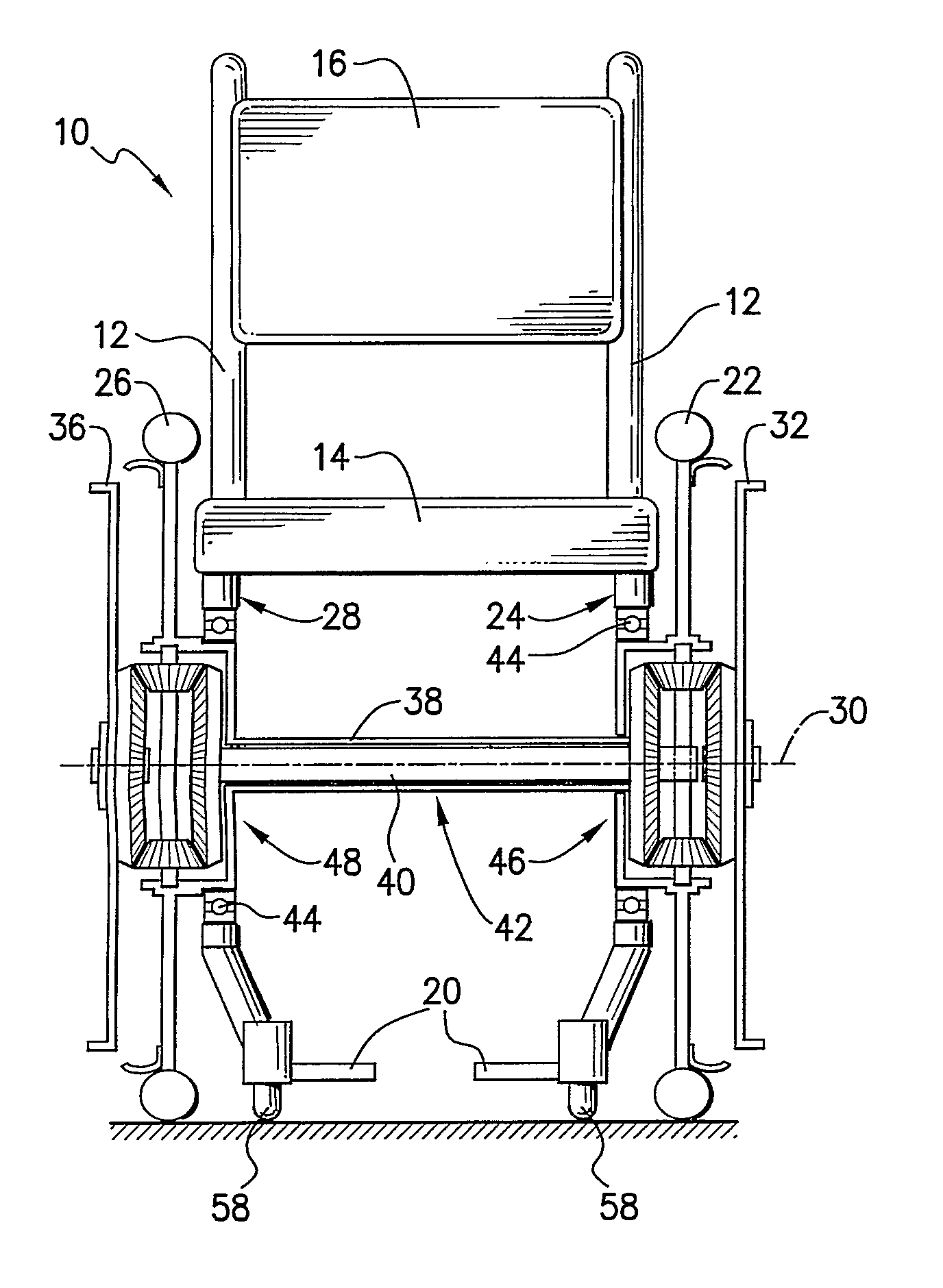
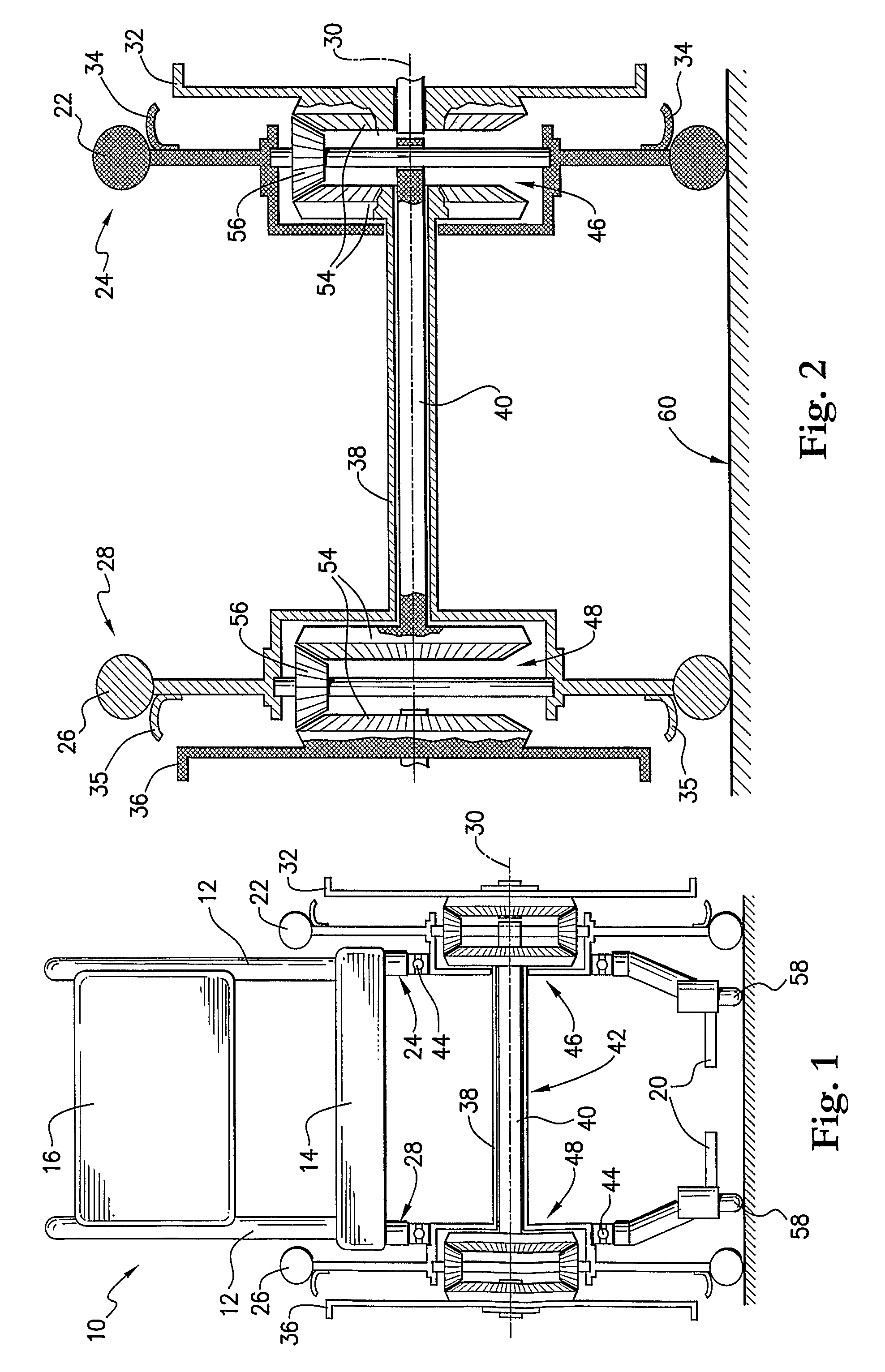
[0067]In FIG. 1 there is shown a wheeled conveyance 10 of any suitable form, for example a wheelchair as shown. Wheelchair 10 includes a frame 12 which carries and supports a seat 14, a backrest 16 and a pair of armrests (not shown). Armrests usually extend outwardly from frame 12, near backrest 16, in a direction substantially parallel to the plane of seat 14. Wheelchair 10 may also include a pair of hand-push handles 18 (see for example FIG. 5) disposed at the uppermost points of frame 12 and which may extend outwardly therefrom in a direction substantially perpendicular to frame 12 and away from the rear of wheelchair 10. Mounted to the base of frame 12 are footrests 20 which are disposed in a position suitable to support the feet of an occupant (not shown). Although shown in FIG. 1 as being two separate footrests 20, it should be understood that a single footrest 20 (see FIG. 5) could be included and the invention is therefore not limited to the specific example as shown.

[0068]W...


PUM


Abstract

A conveyance has a plurality of wheels and, at least, first and second drive axles, which are mounted, or disposed, between the wheels. One of the wheels defines a first wheel that is rotatably mounted to one end of the first drive axle. A second of the wheels is rotatably mounted to one end of the second drive axle. The conveyance further includes a first actuation device for the first drive axle, on the opposite end of the first drive axle from the first wheel and proximate to the second wheel, and a second actuation device for the second drive axle on the opposite end of the second drive axle from the second wheel and proximate the first wheel. The first actuation device is selectively operated to apply a selective relative rotation to the first wheel and the second actuation device is selectively operated to apply a selective relative rotation to the second wheel.

Description

FIELD OF THE INVENTION[0001]The present invention relates, generally, to wheeled conveyance assemblies and relates particularly, though not exclusively, to a manually-operated wheelchair which can be controlled and steered by either or both arms of an occupant.[0002]Throughout the ensuing description the expressions “single-handed occupant(s)” and “two-handed occupant(s)” are intended to refer to persons who have one or two usable hands or arms respectively.BACKGROUND OF THE INVENTION[0003]Manually-operated wheelchairs are well known. Most prior art manually-operated wheelchairs have been designed for two-handed operation by persons, as for example paraplegics, having full or partial use of both hands. Typically, a wheelchair is movably supported by two larger rear wheels and two smaller forward (generally swivel-type) wheels. These wheelchairs are manually-driven or operated by an occupant gripping top portions of the larger rear wheels (or hand-rim assemblies directly connected to...

Claims


Application Information

Patent Timeline
Patent Type & Authority Patents(United States)
IPC IPC(8): B62M1/14
CPCA61G5/02A61G5/08B60B35/14A61G2005/0891A61G2005/0825A61G5/0825A61G5/0891
Inventor BIDWELL, ALANBIDWELL, ADRIAN
Owner BIDWELL ALAN
Why Eureka
Try Eureka