Electrical linear drive

a linear drive and linear drive technology, applied in the direction of electrical apparatus, dynamo-electric machines, printed circuits, etc., can solve the problems of interfering with the installation of the linear drive device, being subject to other kinds of mechanical disorders, easily attracted to dirt,

Inactive Publication Date: 2011-07-05
FESTO AG & CO KG
View PDF13 Cites 3 Cited by
  • Summary
  • Abstract
  • Description
  • Claims
  • Application Information

AI Technical Summary

Benefits of technology

[0008]One object of the present invention is to provide measures for an electrical linear drive device of the type initially mentioned, which are conducive to installation at the place of use while providing satisfactory protection against mechanical damage and optimized electrical communication features.
[0010]The accommodation in a fashion screened off from the outside of the drive part in the accommodation space of the outer housing serves to provide for reliable protection against mechanical damage. In the same manner the electrical cables are safeguarded, which extend in at least one cable channel in the wall of the housing tube toward the central electrical interface means. Since the same is arranged laterally on the housing tube, the end sides of the outer housing are free for assembly operations, being more particularly the possibility of so placing the electrical interface means so that it does not protrude past either of the two end sides of the outer housing. Even during the manufacture of the housing tube it is possible to customize things so that the position of assembly for the installation of the central electrical interface means are prepared, more especially in the form of a through hole extending through the housing wall to the at least one cable channel. Starting at the central electrical interface means separate electrical cables lead to the drive coil arrangement and to the position detecting means, something which allows such laying thereof that the interfering fields of the quite substantial high coil currents do not impair the sensor signals. Accordingly, even without any complex screening measures for the electrical cables it is possible to achieve a reliable manner of operation with a high degree of precision. Finally owing to the outer housing made up of the housing tube and the two housing covers there is a possibility to having mechanical attachment interfaces, which correspond to those in the case of fluid operated linear drives. More particularly, it is possible to realize standard interfaces present in the case of fluid power linear drives. This generally opens up the possibility of installing the electrical linear drive device instead of fluid operated linear drives without rearrangement of adjacent equipment. A system of a machine may consequently be refitted quite simply for electrical drive technology.
[0014]It is an advantage if the electrical cables are inserted into the outer housing through one or both housing covers. Accordingly corresponding transverse channels in the wall of the housing tube are unnecessary. It is possible to trim the housing tube to any required length for customization, without ever involving further later trimming for internally arranged channels.
[0016]An arrangement is more especially advantageous in which the at least one operation cable and the at least one signal cable extend from opposite end sides of the housing tube to the central electrical interface means. This avoids an axial overlap of such cables and prevents in a particularly effective fashion any mutual impairment owing to resulting electrical interference.
[0023]Since the electrodynamic linear direct drive is inclined to suffer from substantial overheating, it is an advantage if axially extending cooling ribs are provided on the outer periphery of the housing tube.
[0024]Finally it is advantageous if on at least one and preferably on both housing covers mechanical attachment interfaces are provided, which render possible an external attachment of the linear drive device and / or the mounting here of additional parts.

Problems solved by technology

This rear arrangement of the central electrical interface means often interferes with the installation of the linear drive device at the site of installation.
Furthermore the drive part at the end is more or less exposed in the output housing and may readily attract dirt or be subject to other kinds of mechanical disorders.

Method used


Image

  • Electrical linear drive
  • Electrical linear drive
  • Electrical linear drive

Examples


Embodiment Construction

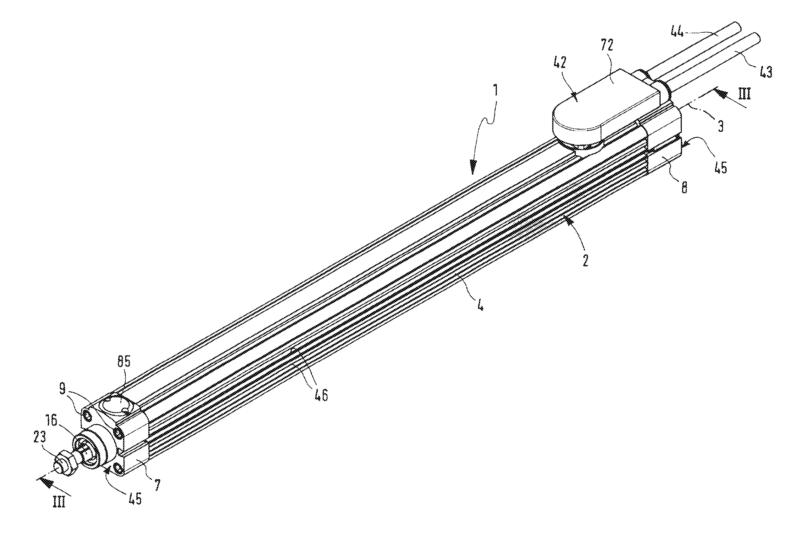
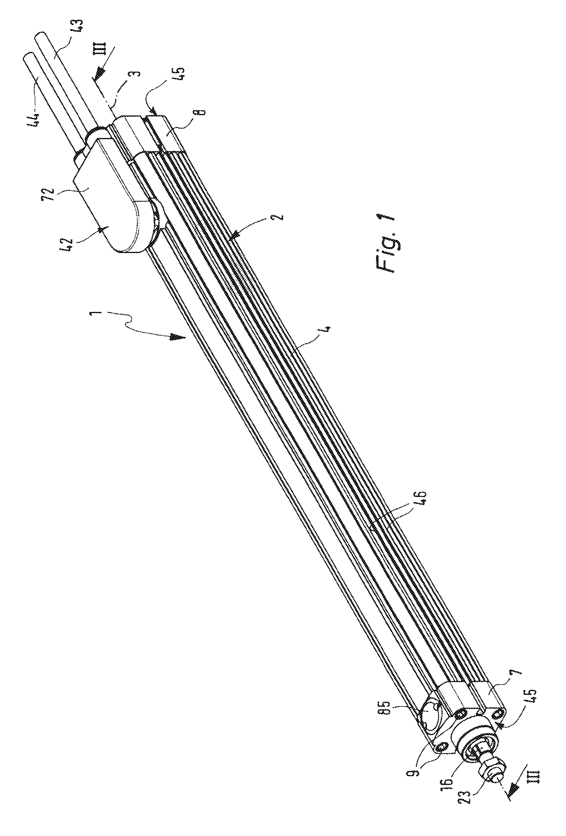
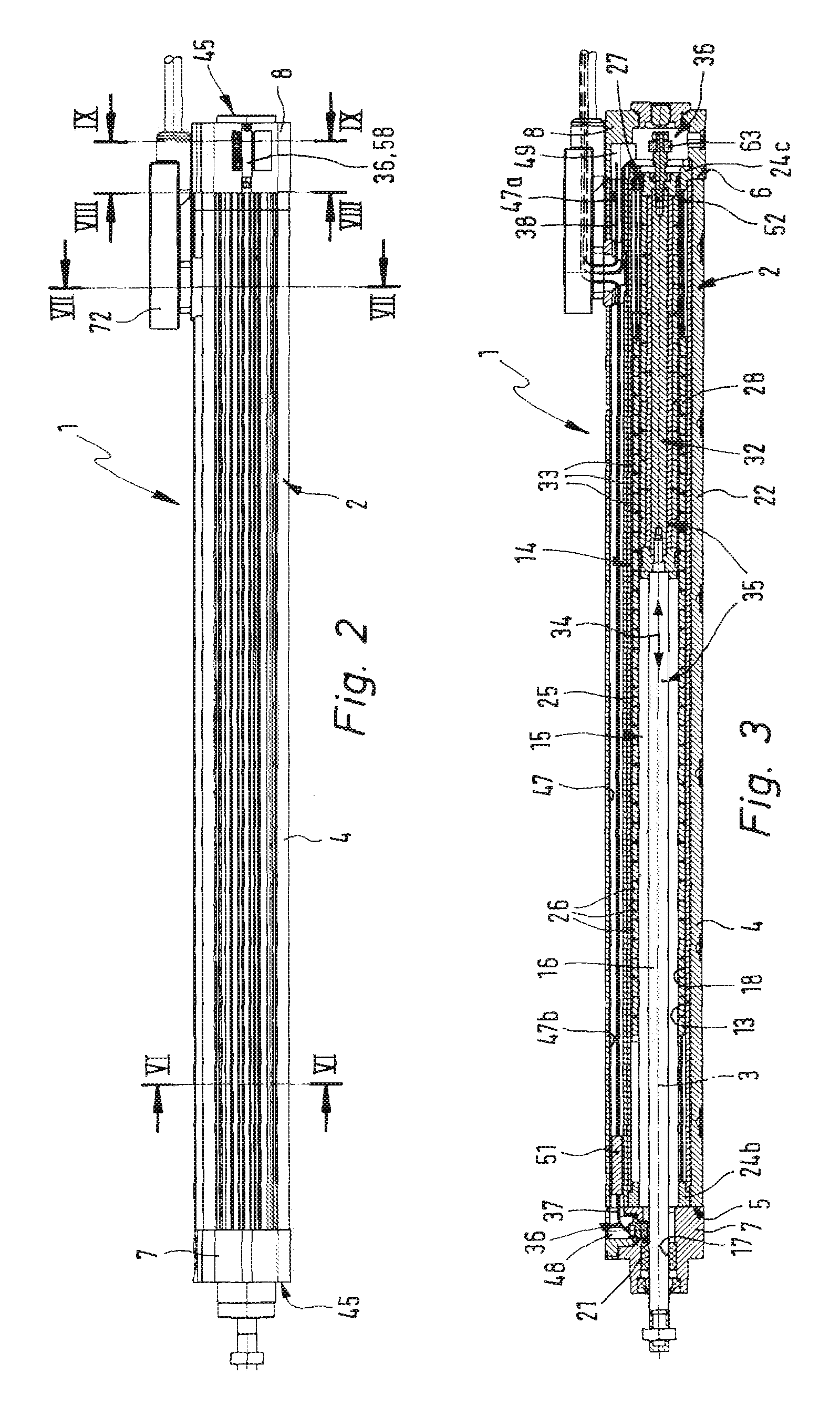
[0035]The electrical linear drive device generally referenced 1 possesses an outer housing 2 with a longitudinal extent, whose longitudinal axis is referenced 3. The outer housing 2 is composed of an elongated housing tube 4, a front housing cover 7 mounted on the front end face 5 of the housing tube 4 and a rear housing cover 8 on the end face 6 of the housing tube 4. The housing covers 7 and 8 are braced axially by axial attachment screws 9 onto the housing tube 4 in a detachable manner.

[0036]The housing tube 4 and the two housing covers 7 and 8 jointly define a receiving space 13 with an essentially cylindrical outline. In this space there is a cartridge-like drive part 14 of a electrodynamic linear drive as a electrical drive unit 15. An output drive rod 16, protruding from the drive part 14 at the front end side, of the drive unit 15, extends through a coaxial opening 17 in the front housing cover.

[0037]During assembly of the linear drive device 1, prior to the attachment of th...


PUM


Abstract

An electrical linear drive device comprises an outer housing consisting of a housing tube and two housing covers disposed at the ends thereof The outer housing defines in the interior thereof a receiving space, into which the drive part of a drive unit in the form of an electrodynamic linear direct drive like a cartridge is placed, and an output drive rod extends outward through the front housing cover. From a drive coil arrangement of the drive unit an electrical operation cable extends to an central electrical interface means. The electrical interface means is disposed laterally on the housing tube and the operation cable and the signal cable extend in a cable channel formed in the wall of the housing tube.

Description

CROSS-REFERENCE TO RELATED APPLICATION[0001]This application claims priority based on European Application No. 07 016 879.4, filed on Aug. 29, 2007, which is incorporated herein by reference.BACKGROUND OF THE INVENTION[0002]1. Field of the Invention[0003]The invention relates to an electrical linear drive device comprising an outer housing, in which the drive part of a drive unit designed in the form of an electrodynamic linear direct drive is inserted axially like a cartridge so that an output drive rod of the drive unit protrudes from the front side of the outer housing, and the drive part has an external drive housing that accommodates a stationary drive coil arrangement and an axially movable armature, which is connected with the output drive rod and has a drive magnet arrangement, a position detecting means for the detection of at least one axial position of the movable unit comprising the armature and the output drive rod, and a central electrical interface means, connected bo...

Claims


Application Information

Patent Timeline
Patent Type & Authority Patents(United States)
IPC IPC(8): H02K41/02H01R12/00H02K33/00
CPCH02K5/225H02K41/03H02K11/0015H02K11/21H02K41/02H02K41/00
Inventor FINKBEINER, MATTHIASGUCKEL, JURGEN
Owner FESTO AG & CO KG
Why Eureka
Try Eureka