Driving signal generating device and related method for display device

a signal generation and display device technology, applied in the direction of instruments, computing, electric digital data processing, etc., can solve the problems of affecting image quality, inaccurate display of grayscale values and line effects of images, and longer time corresponding to central pixels of the panel, so as to prevent image crosstalk

Inactive Publication Date: 2011-07-19
NOVATEK MICROELECTRONICS CORP
View PDF3 Cites 1 Cited by
  • Summary
  • Abstract
  • Description
  • Claims
  • Application Information

AI Technical Summary

Benefits of technology

[0010]It is therefore a primary object of the present invention to provide a driving signal generating device and related method for staggering transition time of driving signals to prevent image crosstalk for a display device.

Problems solved by technology

The passive TN and STN LCDs both utilize field voltages to drive the liquid crystals so that response times corresponding to central pixels of the panel may become longer with increase of the panel size, affecting image quality.
Since the liquid crystals may lose flexibility of polarization under long-term driving by same voltage, the display device requires voltage signals having different polarities to drive the liquid crystals when an image is displayed in continuous frames.
The grayscale waveforms of the neighboring segment electrodes interact with each other, resulting in inaccurate display of grayscale values and line effects of images.
Moreover, the grayscale waveforms are not perfect in implementation and thereby react to transitions (rising or falling) with response times. Therefore, the neighboring segment electrodes will simultaneously demand transition current if the neighboring pixels have the same grayscale value.
This challenges system circuits and due to huge workload, the response time may be extended, increasing root-mean-square (RMS) loss of transition current.
In this situation, the fully black or white pixels show stronger grayscale depths than other pixels do due to no current loss, resulting in an unbalanced image.
The grayscale waveforms are thus affected by each other such that crosstalk happens between the neighboring segment electrodes, resulting in image distortion.

Method used


Image

  • Driving signal generating device and related method for display device
  • Driving signal generating device and related method for display device
  • Driving signal generating device and related method for display device

Examples


Embodiment Construction

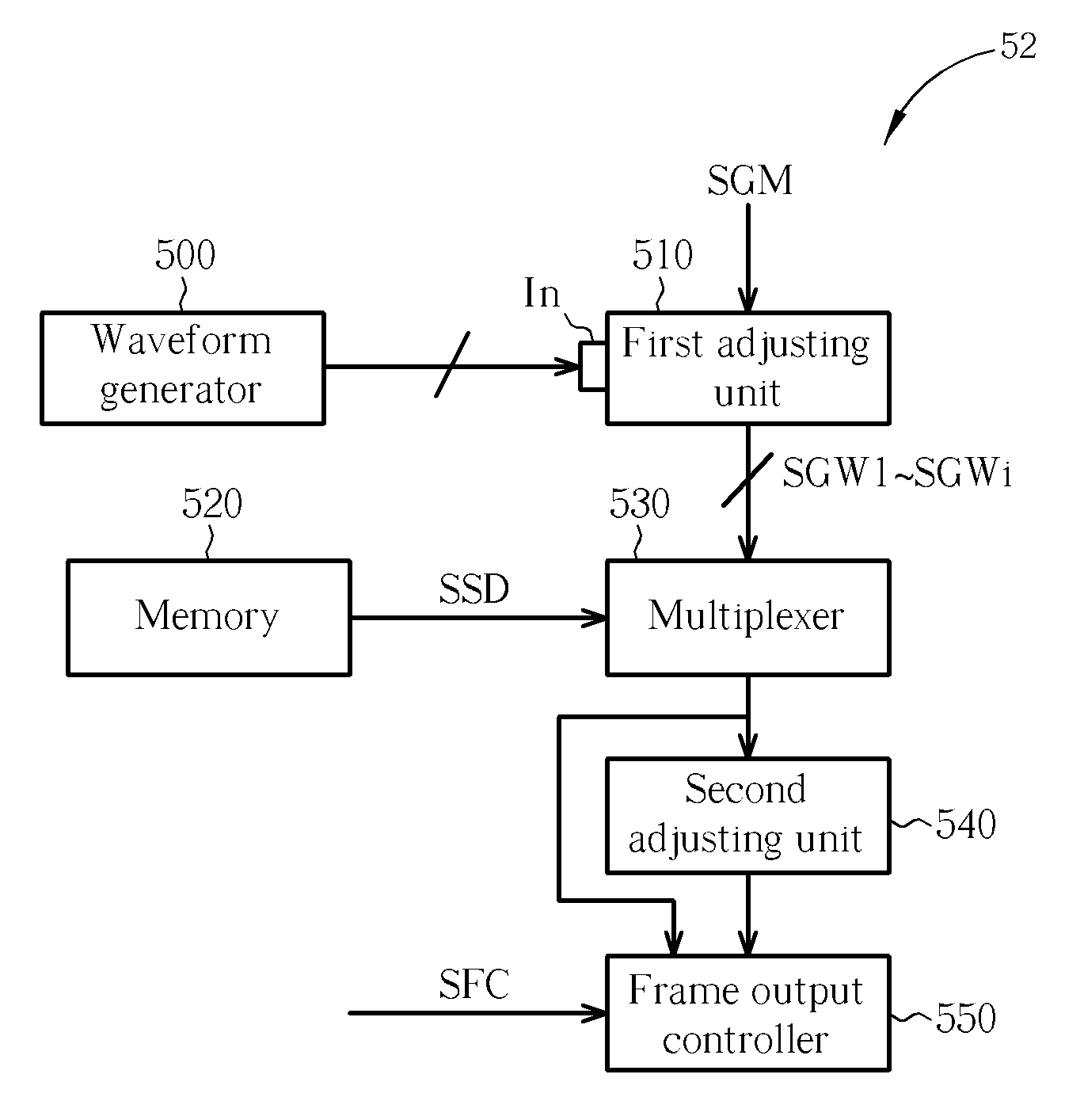
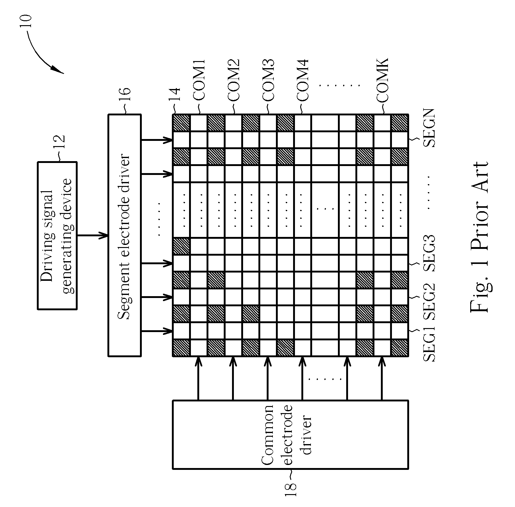
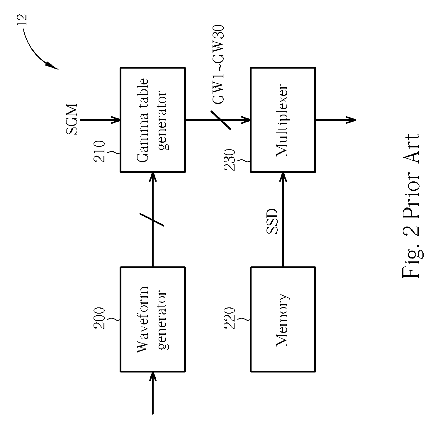
[0020]Please refer to FIG. 5, which is a schematic diagram of a driving signal generating device 52 according to an embodiment of the present invention. The driving signal generating device 52 is applied to a passive display device for staggering transition time of driving signals outputted from segment electrodes in the passive display device. The passive display device is capable of displaying i gray scales (assume that the grayscale values are 1−i), and the architecture thereof is similar to that of the display device 10 in FIG. 1. Here, the driving signal generating device 52 is adopted to replace the driving signal generating device 12, and includes a waveform generator 500, a receiving terminal In, a first adjusting unit 510, a memory 520, a multiplexer 530, a second adjusting unit 540 and a frame output controller 550. The receiving terminal In is used for receiving i step grayscale waveforms generated by the waveform generator 500. The first adjusting unit 510 is a gamma tab...


PUM


Abstract

A driving signal generating device for staggering transition time of driving signals to prevent image crosstalk for a display device includes a receiving terminal, a first adjusting unit, a multiplexer, a second adjusting unit and a frame output controller. The receiving terminal receives a plurality of step grayscale waveforms. The first adjusting unit transforms the plurality of step grayscale waveforms into a plurality of initial grayscale waveforms and further adjusts widths of the plurality of initial grayscale waveforms according to a first predetermined value to generate a plurality of grayscale waveforms. The multiplexer selects a first grayscale waveform from the plurality of grayscale waveforms. The second adjusting unit then adjusts a width of the first grayscale waveform according to a second predetermined value to generate a second grayscale waveform. The frame output controller controls output of the first grayscale waveform and the second grayscale waveform.

Description

BACKGROUND OF THE INVENTION[0001]1. Field of the Invention[0002]The present invention relates to a circuit device and related method for a display device, and more particularly, to a driving signal generating device for staggering transition time of driving signals to prevent image crosstalk for a display device.[0003]2. Description of the Prior Art[0004]With vigorous growth in electronic industrials, a liquid crystal display (LCD) has been widely used in various application fields and the market demand thereof has been increasing rapidly. The operating principle of the LCD is that the LCD utilizes different voltages to drive liquid crystals to arrange in different aspects so as to control the light penetrating amount for each pixel of an image. According to driving manners, the LCD can be divided into three types: Static, Simple Matrix and Active Matrix. The simple matrix type is called a passive type as well, having two models of twisted nematic (TN) and super twisted nematic (STN...

Claims


Application Information

Patent Timeline
Patent Type & Authority Patents(United States)
IPC IPC(8): G09G3/36
CPCG09G3/2014G09G3/3614G09G3/3622G09G2320/0209
Inventor CHEN, JIUN-TINGCHOU, WEN-PINGKUO, FENG-JUNGCHANG, KUEI-CHUNG
Owner NOVATEK MICROELECTRONICS CORP
Why Eureka
Try Eureka