Apparatus for printing on the plant surface and the artificial plant surface

a technology for plants and artificial plants, applied in the field of printers, can solve the problems of insuperable deficiency, complicated plate-making that is necessary for all kinds of printing, and prevent the popularity of the technology from meeting the requirements of most people,

Inactive Publication Date: 2011-08-02
PANASONIC CORP
View PDF13 Cites 8 Cited by
  • Summary
  • Abstract
  • Description
  • Claims
  • Application Information

AI Technical Summary

Benefits of technology

[0007]An object of the present invention is to provide an apparatus for printing clear, beautiful, flamboyant and elective image on surfaces of plant and artificial plant so that the plant may transfer more earnest and rich emotion and make more romantic feeling.
[0023]3. The operation is controlled in program through a micro camera such that the printing effect can be reviewed, the image can be zoomed and rotated. The printing procedure is display in real time and can be effectively controlled.

Problems solved by technology

Although personal requirements can be met by this way, the printing possesses an insuperable deficiency, that's, the plate-making that is necessary to all kinds of printing is complicated in processing, time-wasting, and labor-wasting, which is a bottleneck that restricts development of the technology and prevents the technology from being popular and meeting the requirement of most people.
However, the method is too complicated in processing to be popularly and wildly utilized.
Thus it can be seen that it is not a good choice to provide images onto the plant surface and the artificial plant surface through printing.
However, among the current types of prints, the applications of laser print and hot transfer print are limited because of the part high temperatures of the print heads and the pressures between the print heads and the mediums.
They can not be used onto the delicate articles such as the above mentioned plant and artificial plant.
However, limited by the shapes of the plant and the artificial plant, obviously traditional ink jet print can not be used, for they can not enter the paper path as paper sheets.
However, an apparatus with specific structure, which can be used to directly print image on the surfaces of plant and artificial plant, does not come into people's eyes.

Method used


Image

  • Apparatus for printing on the plant surface and the artificial plant surface
  • Apparatus for printing on the plant surface and the artificial plant surface
  • Apparatus for printing on the plant surface and the artificial plant surface

Examples


embodiment 1

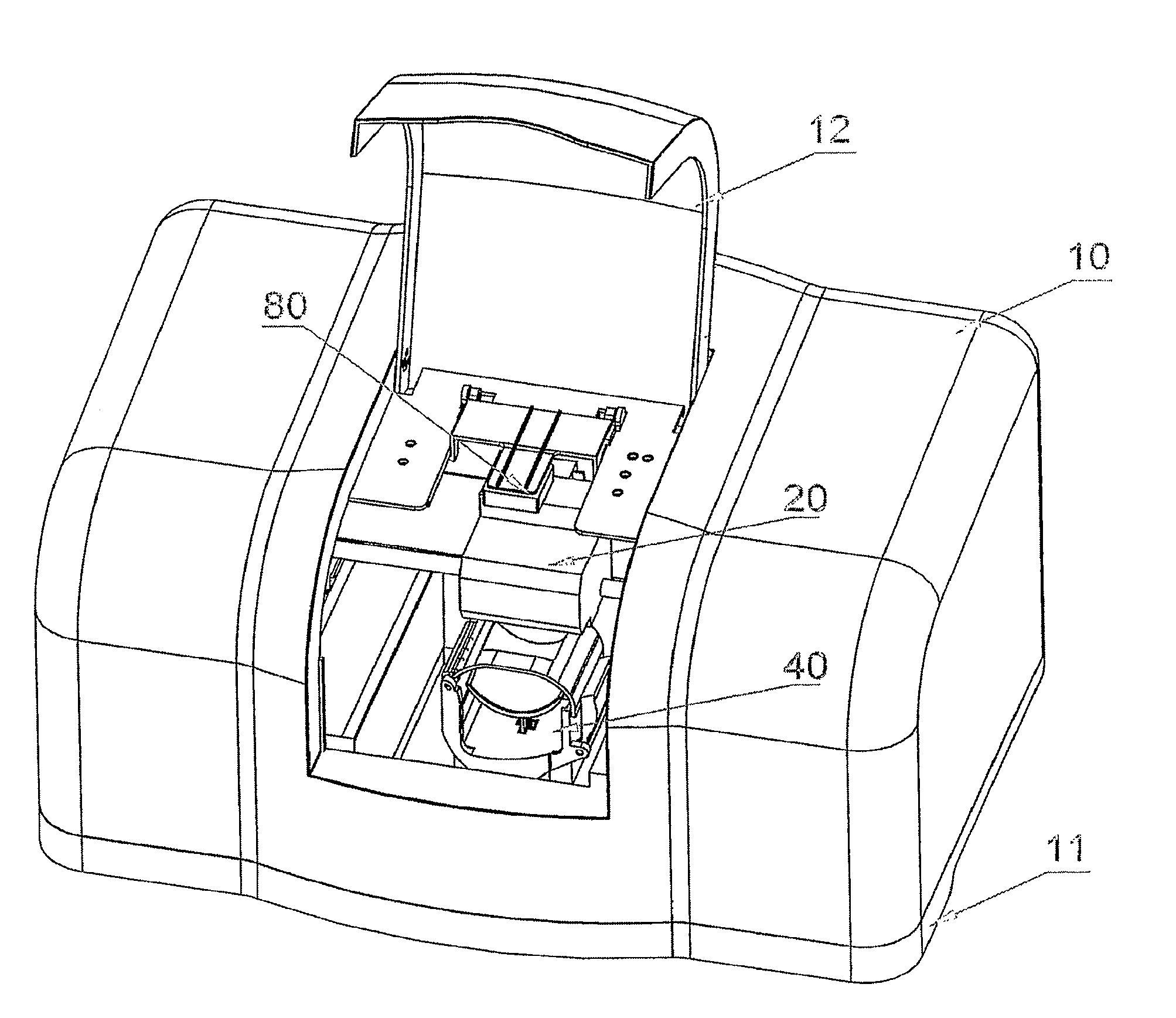
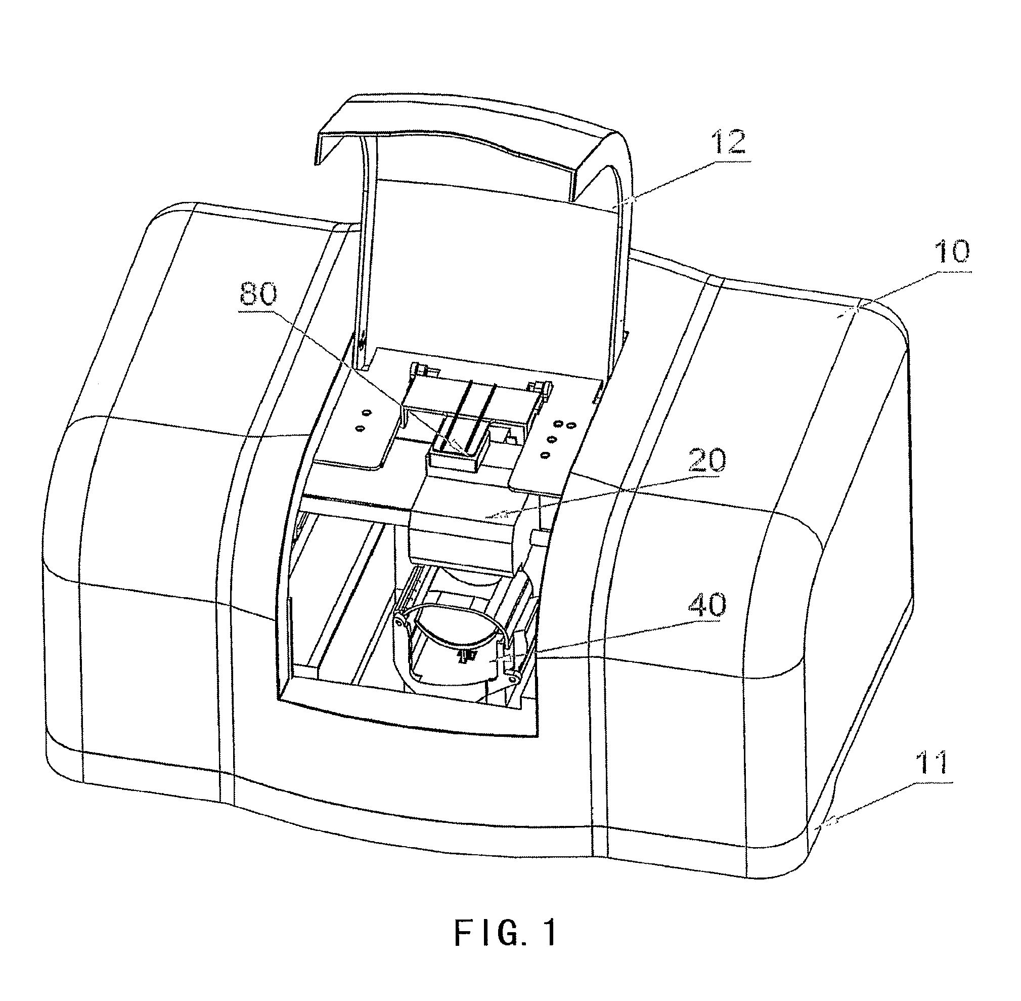
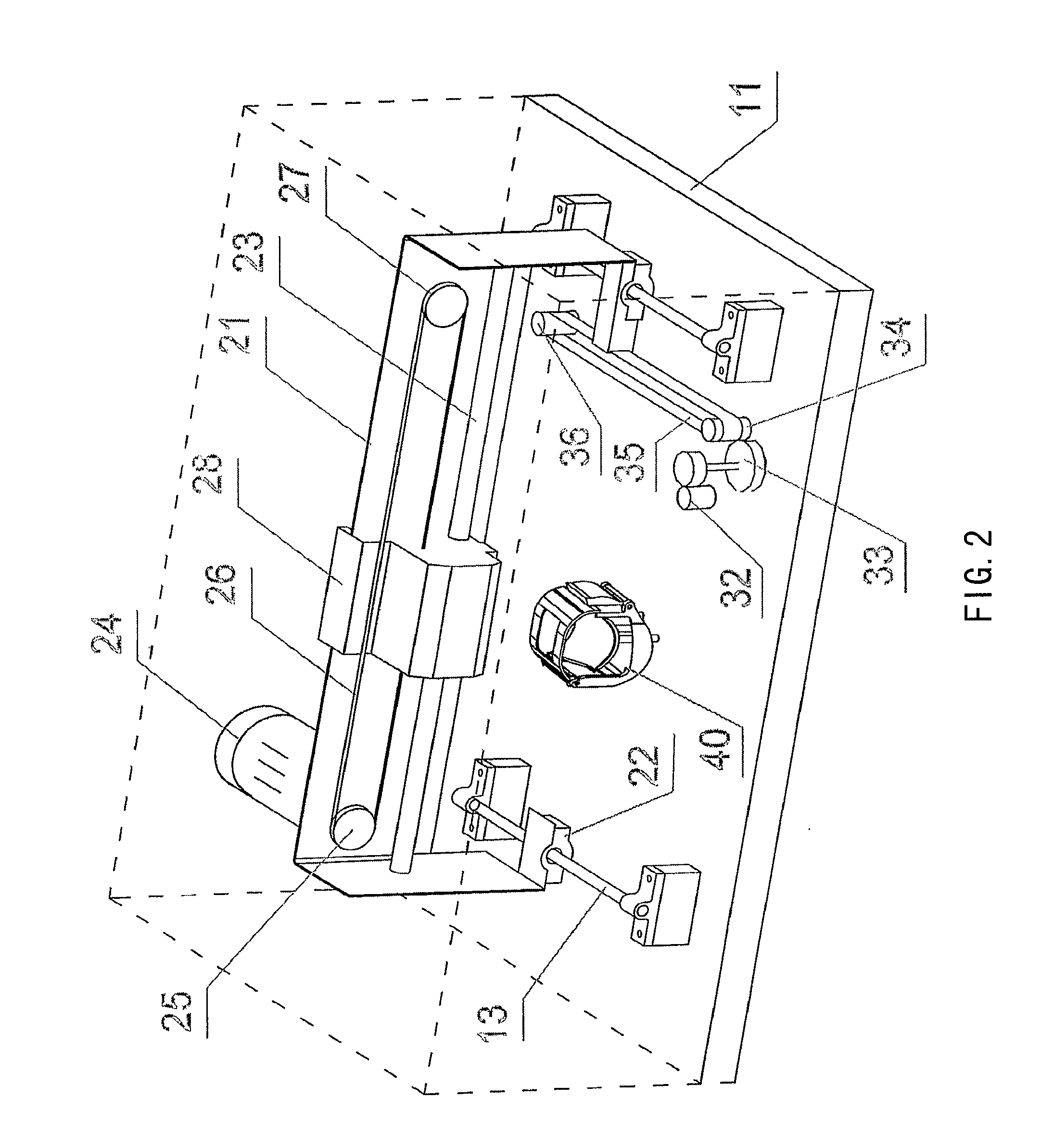
[0034]The embodiment is for printing on the flower and the artificial flower. As shown in FIG. 1, it comprises a housing 10 which are comprised of a base 11 and a cover 12 hinged to the base 11. Two horizontal guiding posts 13 parallel to each other are longitudinally fixed on the base 11, and two corresponding guiding sleeves 22 are disposed on the bottom of the printing bracket 21. A bracket motor 32 is fixed on the base 11. The bracket motor 32 is associated with an active belt pulley 34 with gear teeth through a gear reducer 33, and the active belt pulley 34 is associated with a driven belt pulley 36 through toothed belt 35 which is fixed on a position of the base 11. The active belt pulley 34, the belt 35 and the driven belt pulley 36 constitute a transmission mechanism 30. Through the gear reducer 33 and the transmission mechanism 30, the rotation of shaft of the bracket motor 32 drives the printing bracket 21 to slide along the guiding post 13, as shown in FIG. 2.

[0035]A trav...

embodiment 2

[0042]Compared with the embodiment 1, the computer device 70 of embodiment 2 is integrated in the housing 10. Display device and input device are mounted on the surface of the housing 10. The circuit diagram is as shown in FIG. 5. Display module, memory module, input module, communication module, account module and printing module are connected to the control unit through a bus. The control unit is comprised of at least a programmable logic-controlled integrated circuit and a peripheral matchable circuit. I / O ports of the programmable logic-controlled integrated circuit are connected with the corresponding ports of the display module, memory module, input module, communication module, account module and printing module through the bus. The memory module is comprised of at least an external memorizer and an external connecting interface for the external memorizer. The input module is a touch screen or a set of panel micro switches. The programmable logic-controlled integrated circuit...

embodiment 3

[0057]As shown in FIG. 8, compared with the embodiment 1, the transmission mechanism is comprised of a bracket motor 32 fixed on the base 11. The bracket motor 32 is coupled to an active belt pulley 34, and the active belt pulley 34 is coupled to a driven belt pulley 36 through a belt 35 which is fixed at the bottom of the left end of the printing bracket 21 on a position thereof. At the same time, an aid belt pulley 37 and a second driven belt pulley 38 are disposed on the other end of the printing bracket 21. The active belt pulley 34 is coupled to the second driven belt pulley 38 through a second belt 39 which surrounds the aid belt pulley 37. The part of the second belt 39 between the aid belt pulley 37 and the second driven belt pulley 38 is parallel to the guiding post 13 and is fixed with one end of the printing bracket 21 on a corresponding position thereof. In use, the bracket motor 32 rotates, so that the active belt pulley 34 drives the two ends of the printing bracket 21...


PUM


Abstract

An apparatus for printing on the plant surface and the artificial plant surface, comprises a housing. A gripping device for holding the plant or artificial plant and a printing unit for printing on its surfaces are disposed in said housing. Said printing unit is connected to a computer which is external or integrated in the housing. The printing unit of the present invention is an ink jetting unit, which can print on the plant surface and the artificial plant surface, especially flower, artificial flower, leaves and the fruit. People can communicate information using these articles, which satisfied the demand.

Description

TECHNICAL FIELD[0001]The present invention relates to a printer, in particular an apparatus for printing images on surfaces of plant or artificial plant.BACKGROUND ART[0002]In life, plant or artificial plant, such as flower, artificial flower, red leaf and fruit, are mutually presented among people in order to express sentiments. Accompanying with people's more and more intense desire of fashion seeking and showing individuality, people wish to provide self-defined images onto those articles to express personal thinking and sentiments.[0003]Presently, printing is adopted as the way of providing images on plant surface or artificial plant surface. Although personal requirements can be met by this way, the printing possesses an insuperable deficiency, that's, the plate-making that is necessary to all kinds of printing is complicated in processing, time-wasting, and labor-wasting, which is a bottleneck that restricts development of the technology and prevents the technology from being ...

Claims


Application Information

Patent Timeline
Patent Type & Authority Patents(United States)
IPC IPC(8): B41F17/00
CPCA01G7/06B41J3/4073B44C5/06B41J3/40731
Inventor WANG, HONG
Owner PANASONIC CORP
Why Eureka
Try Eureka