Drive mechanism with foot platform angle adjustment mechanism for elliptically-driven device

a technology of elliptical drive and foot platform, which is applied in the direction of marine propulsion, gymnastic exercise, and boat construction, etc., can solve the problems of extreme foot platform angle that is uncomfortable for the elliptical cycle rider, undue stress on the rider's knee and ankle joints, and reduce the overall length of the elliptical drive device. , the effect of weight and cost reduction

Active Publication Date: 2020-06-30
PT MOTION WORKS INC
View PDF39 Cites 1 Cited by
  • Summary
  • Abstract
  • Description
  • Claims
  • Application Information

AI Technical Summary

Benefits of technology

[0005]An aspect of the invention involves a camming foot platform on an elliptically-driven device. A camming foot platform allows the foot platform angle to vary relative to the drive arm angle throughout the pedaling stroke while still maintaining the feel of a stable platform to stand upon at all times. This allows for the use of a shorter drive arm than would be possible with a fixed foot platform to achieve a desired generally elliptical or ovate foot path without the feeling of instability that accompanies a pivoting platform. The shorter drive arm enables a reduction in the overall length of the elliptically-driven device's frame with a corresponding reduction in weight and cost. The camming foot platform's stability compared with a pivoting foot platform makes the rider feel more secure and less fatigued while riding. In some embodiments of the camming foot platform, the platform is large enough to enable the rider to significantly vary their foot position while riding which changes the foot path and workout experience. Elliptical cycles with simple pivoting foot platforms known in the art are constrained to one foot path while riding because the rider must maintain balance about the pivot point of the platform which is in a fixed location while riding.
[0007]In the example of an elliptical cycle, human anatomy limits the range of foot angles that are viable for powering an elliptical cycle. Extreme foot platform angles can be uncomfortable for the elliptical cycle rider. If the angle is too extreme at the top of the power stroke, it can put undue stress on the rider's knee and ankle joints. If the angle is too extreme at the bottom of the power stroke, it can aggravate the rider's Achilles tendon. Over time, either of these extremes can lead to injuries. For an elliptical cycle with fixed foot platforms attached directly to the drive arm, the pedal angle during the pedal stroke is determined by the drive arm angle. In turn, the drive arm angle during the pedal stroke is directly related to the length of the drive arm, the length of the crank arm to which it is attached and the crank pivot offset from the reciprocating axis. For a given crank arm length and crank pivot offset, shortening the drive arm increases the drive arm angles at both the top and bottom of the power stroke. For a given crank arm length and drive arm length, reducing the crank pivot offset decreases the drive arm angles at both the top and bottom of the power stroke. As a result, for elliptical cycles with fixed platforms, there is a minimum drive arm length that is viable for a given crank arm length and crank pivot offset. By using a camming foot platform, this minimum drive arm length can be shortened because the angle of the foot platform is determined by the camming system, not the angle of the drive arm. The camming system can be designed to ensure that the foot angle throughout the pedaling stroke is always at a comfortable angle even when the drive arm is at an angle that would be too extreme to be comfortable with a fixed foot platform. The drive arm length impacts the overall length of an elliptical cycle and the size of the frame. Shortening the drive arms can allow for the use of a smaller frame, which can result in significant cost savings for the manufacturer.

Problems solved by technology

In the example of an elliptical cycle, human anatomy limits the range of foot angles that are viable for powering an elliptical cycle.
Extreme foot platform angles can be uncomfortable for the elliptical cycle rider.
If the angle is too extreme at the top of the power stroke, it can put undue stress on the rider's knee and ankle joints.
If the angle is too extreme at the bottom of the power stroke, it can aggravate the rider's Achilles tendon.
Over time, either of these extremes can lead to injuries.

Method used


Image

  • Drive mechanism with foot platform angle adjustment mechanism for elliptically-driven device
  • Drive mechanism with foot platform angle adjustment mechanism for elliptically-driven device
  • Drive mechanism with foot platform angle adjustment mechanism for elliptically-driven device

Examples


Embodiment Construction

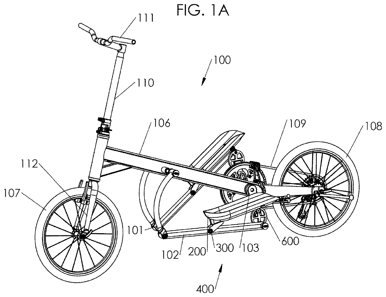
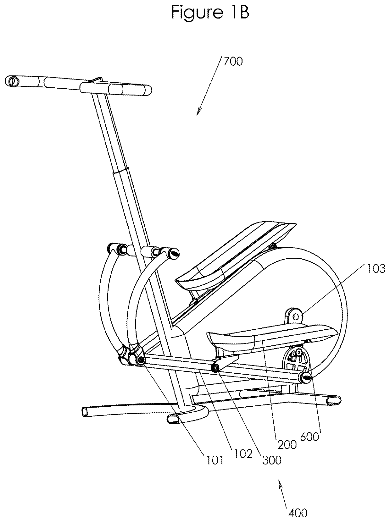
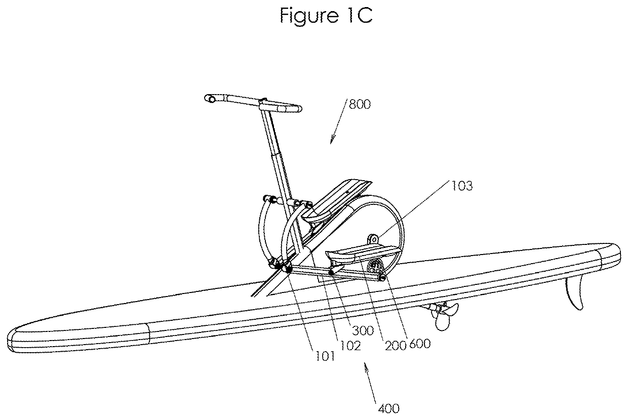
[0083]With reference to FIG. 1A, an embodiment of a rear-drive elliptical cycle 100 with short drive arms and camming foot platforms is shown. Before describing the camming foot platforms, the elliptical cycle will first be described. In alternative embodiments, the camming foot platforms are applied to other types of elliptically-driven human powered vehicles including, without limitation, elliptical cycles with two, three, or four wheels; elliptical cycles with arm levers in place of the handlebars. In a further embodiment, as shown in FIG. 1B, the camming foot platforms are applied to a stationary elliptical exercise machine 700 for commercial use and / or home use. In a further embodiment, as shown in FIG. 1C, the camming foot platforms are applied to an elliptically-driven watercraft 800. Thus, the camming foot platforms shown and described herein may be applied to elliptically-driven devices such as, but not limited to, elliptical cycles, elliptically-driven watercraft, and stat...


PUM


Abstract

A drive mechanism for an elliptically-driven device includes a drive arm with a foot platform pivot assembly; a crank arm; a foot platform assembly pivotally coupled to the drive arm via the foot platform pivot assembly; a foot platform angle adjustment mechanism operably coupling the foot platform assembly to the crank arm so as to impart a foot platform angle of the foot platform assembly relative to the drive arm that varies during a stroke of the foot platform assembly.

Description

CROSS REFERENCE TO RELATED APPLICATION[0001]This application claims the benefit of U.S. Provisional Patent Application No. 62 / 375,990, filed Aug. 17, 2016, which is incorporated by reference herein.BACKGROUNDField of the Invention[0002]The present invention relates generally to elliptically-driven devices, and particularly to foot platforms of elliptically-driven device.Related Art[0003]An elliptical cycle operates by the user standing atop foot platforms and using his legs to stride forward and rearward in a generally elliptical or ovate path causing the rear wheel to rotate and propel the elliptical cycle. Many different versions of the elliptical cycle are known in the art, employing different mechanisms to transfer power from the user to the rear wheel. For example, in one version of an elliptical cycle, an elliptical or ovate path is created by a slider-crank mechanism comprised of guide tracks, drive arms and crank arms where a rear end of each drive arm is attached to a corre...

Claims


Application Information

Patent Timeline
Patent Type & Authority Patents(United States)
IPC IPC(8): A63B22/06B63H16/20A63B22/20B62K3/00B62M1/26A63B22/00A63B21/22
CPCA63B21/227A63B22/0664B62K3/002B62M1/26A63B22/0046A63B22/0015A63B22/0017B63H16/20A63B22/208A63B22/0061A63B22/001A63B2022/0682A63B2022/067
Inventor TEAL, BRENT C.HILL, BRIAN LEE
Owner PT MOTION WORKS INC
Why Eureka
Try Eureka