
LED lamp

a technology of led lamps and lampshades, which is applied in the field of led lamps, can solve the problems of uneven affect the uniformity of the brightness in the illuminating range, and achieve the effect of adjusting the illuminating angl

Inactive Publication Date: 2011-08-09
DAVINCI INDAL
View PDF6 Cites 34 Cited by
  • Summary
  • Abstract
  • Description
  • Claims
  • Application Information

AI Technical Summary

Benefits of technology

"The present invention is an improved LED lamp that can adjust the illuminating angle. It includes a heat dissipating body, a rotating front cover, an LED assembly, a lens assembly, a driving unit, and a socket. The rotating front cover is rotatably disposed in the front side of the heat dissipating body, and the inner wall of the rotating front ring has a screwed channel. The lens assembly is disposed in the heat dissipating body, and the lens moving ring of the lens assembly has a screwed thread mating to the screwed channel. This allows the lens assembly to be moved to adjust the illuminating angle of the LED lamp via rotating the rotating front cover. The technical effect of this invention is that it provides a convenient and easy way to adjust the illuminating angle of an LED lamp."

Problems solved by technology

However, the conventional lamp module has following disadvantages.
Firstly, the height of the lamp posts are different when the street lamp being used in different illuminating situations, the LEDs of the lamp module may only illuminate single direction for the reason of limited emitting angle, then the brightness in the illuminating range are uneven when the lamp module engaged with lamp posts in different height.
Secondly, the lamp module may maintain different angles relative to the ground, which may also impact the uniformity of the brightness in the illuminating range.

Method used


Image

  • LED lamp
  • LED lamp
  • LED lamp

Examples


Embodiment Construction

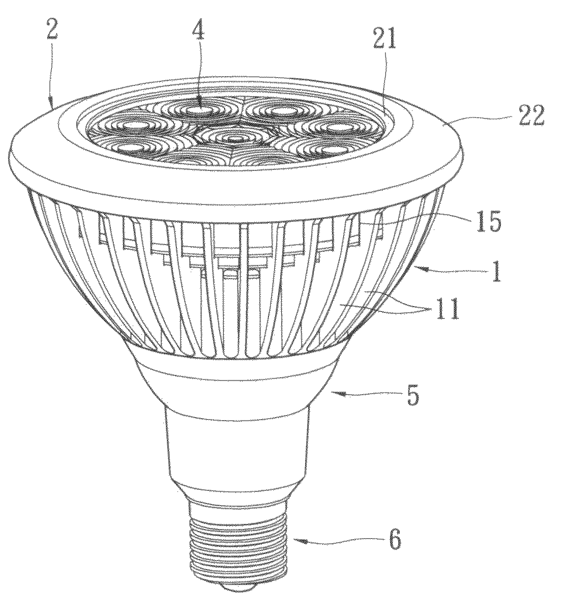
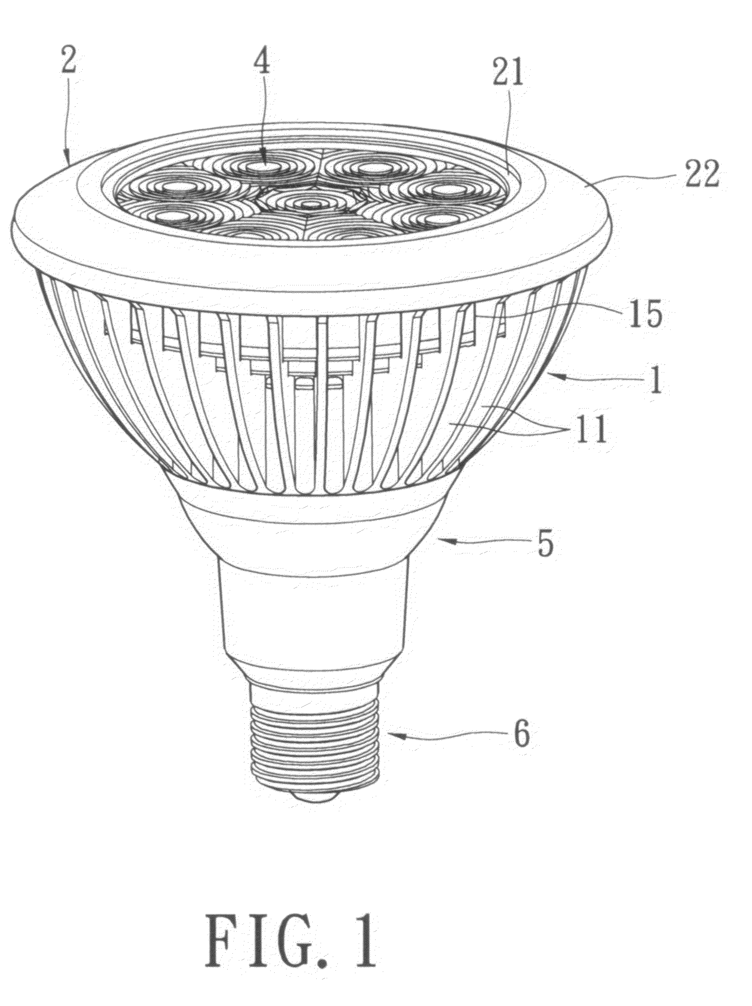
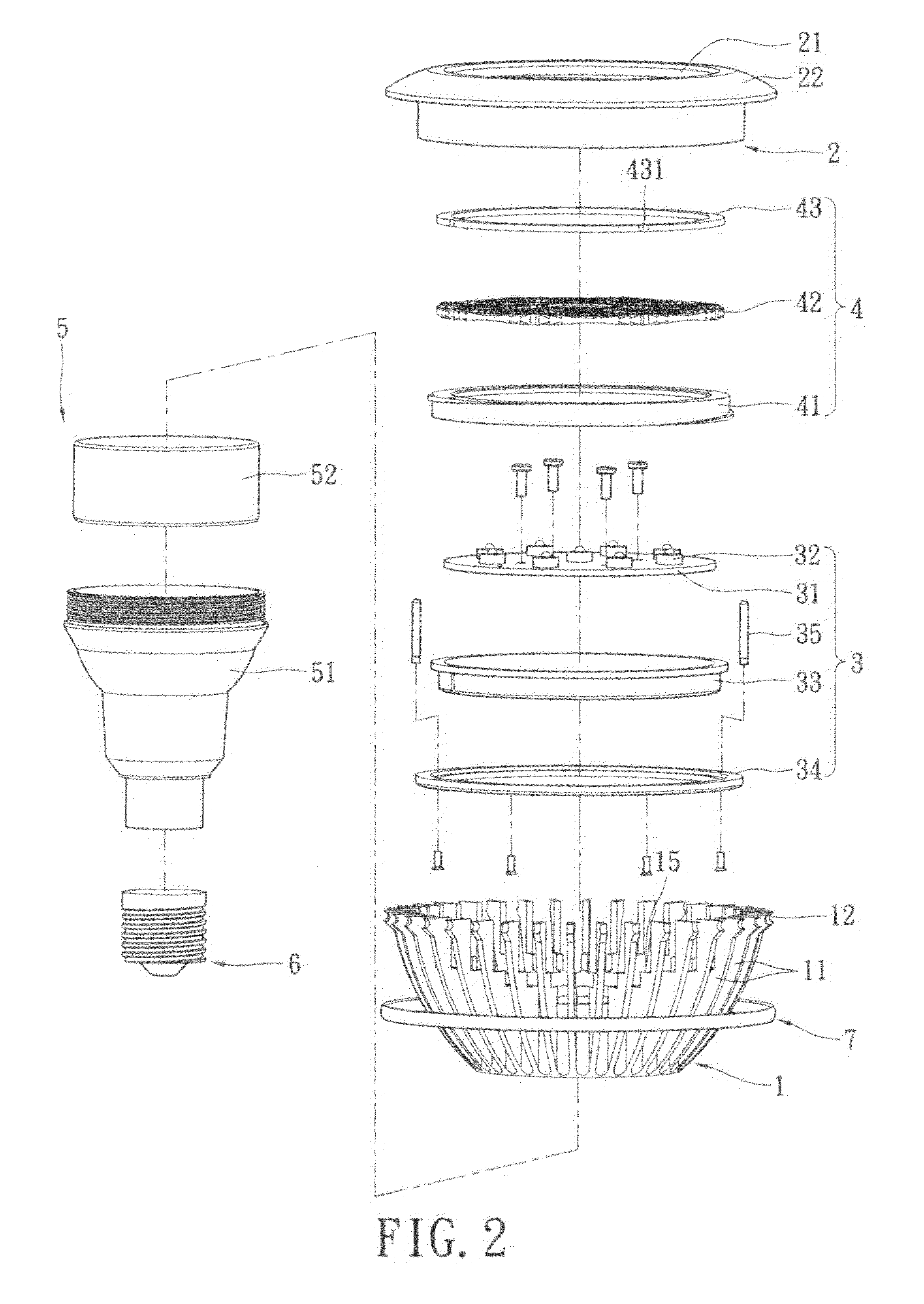
[0016]Please refer to FIGS. 1 to 5. The present invention provides an improved LED lamp, which includes a heat dissipating body 1, a rotating front cover 2, an LED assembly 3, a lens assembly 4, a driving unit 5 and a socket 6.

[0017]The heat dissipating body 1 is shaped into a circle and has high thermal conductivity. In this embodiment, the heat dissipating body 1 has a plurality of fins 11, a fixing groove 12, a first accommodating space 13, a second accommodating space 14, and a heat dissipating groove 15. The fins 11 are located around the heat dissipating body 1 and shaped into a radiate shape. The fixing groove 12 is shaped into a ring and formed around the outside of fins 11 for fixing a heat preventing element 7. The heat dissipating groove 15 is shaped into a ring and formed around the inside of the fins 11 for dissipating heat. The heat dissipating groove 15 can guide air into the heat dissipating body 1 to dissipate heat generated from the LED assembly 3.

[0018]The rotatin...


PUM


Abstract

An LED lamp includes a heat dissipating body, a rotating front cover, an LED assembly, a lens assembly, a driving unit, and a socket. The heat dissipating body has a plurality of fins for dissipating heat. The rotating front cover is rotatably disposed in the front side of the heat dissipating body, the inner wall of the rotating front ring has a screwed channel. The LED assembly is disposed in the heat dissipating body. The lens assembly has a screwed thread mating to the screwed channel and disposed in the heat dissipating body. The lens assembly can be moved via rotating the rotating front cover. As a result, the illuminating angle of the LED lamp is adjustable.

Description

BACKGROUND OF THE INVENTION[0001]1. Field of the Invention[0002]The present invention relates to a LED lamp, and in particular to an improved LED lamp with adjustable illuminating angle.[0003]2. Description of Related Art[0004]Light emitting diode (LED) are used in many applications such as lamps, flat screen displays and devices to provide illumination. LED are small, inexpensive, lower power, long used life, etc., so more and more LED with different capabilities are being developed.[0005]Generally, the LEDs are aligned on a circuit board to form an LED module, and the LEDs of the LED lamp having great illuminative range. However, the conventional lamp module has following disadvantages. Firstly, the height of the lamp posts are different when the street lamp being used in different illuminating situations, the LEDs of the lamp module may only illuminate single direction for the reason of limited emitting angle, then the brightness in the illuminating range are uneven when the lamp...

Claims


Application Information

Patent Timeline
Patent Type & Authority Patents(United States)
IPC IPC(8): F21V21/00
CPCF21V29/83F21V29/773F21K9/137F21Y2101/02F21K9/233F21Y2115/10
Inventor CHIU, HUA-JUNG
Owner DAVINCI INDAL
Learn More