Protective hull for vehicles

a protective hull and vehicle technology, applied in the direction of shields, roofs, transportation and packaging, etc., can solve the problems of vehicle operation in hazardous or dangerous conditions or circumstances that may be subject to trauma, vehicle may be subject to substantial force rendered by explosives

Inactive Publication Date: 2011-08-16
COX TIMOTHY J
View PDF17 Cites 86 Cited by
  • Summary
  • Abstract
  • Description
  • Claims
  • Application Information

AI Technical Summary

Problems solved by technology

Vehicles operating in hazardous or dangerous conditions or circumstances may be subject to trauma from un

Method used


Image

  • Protective hull for vehicles
  • Protective hull for vehicles
  • Protective hull for vehicles

Examples


Embodiment Construction

)

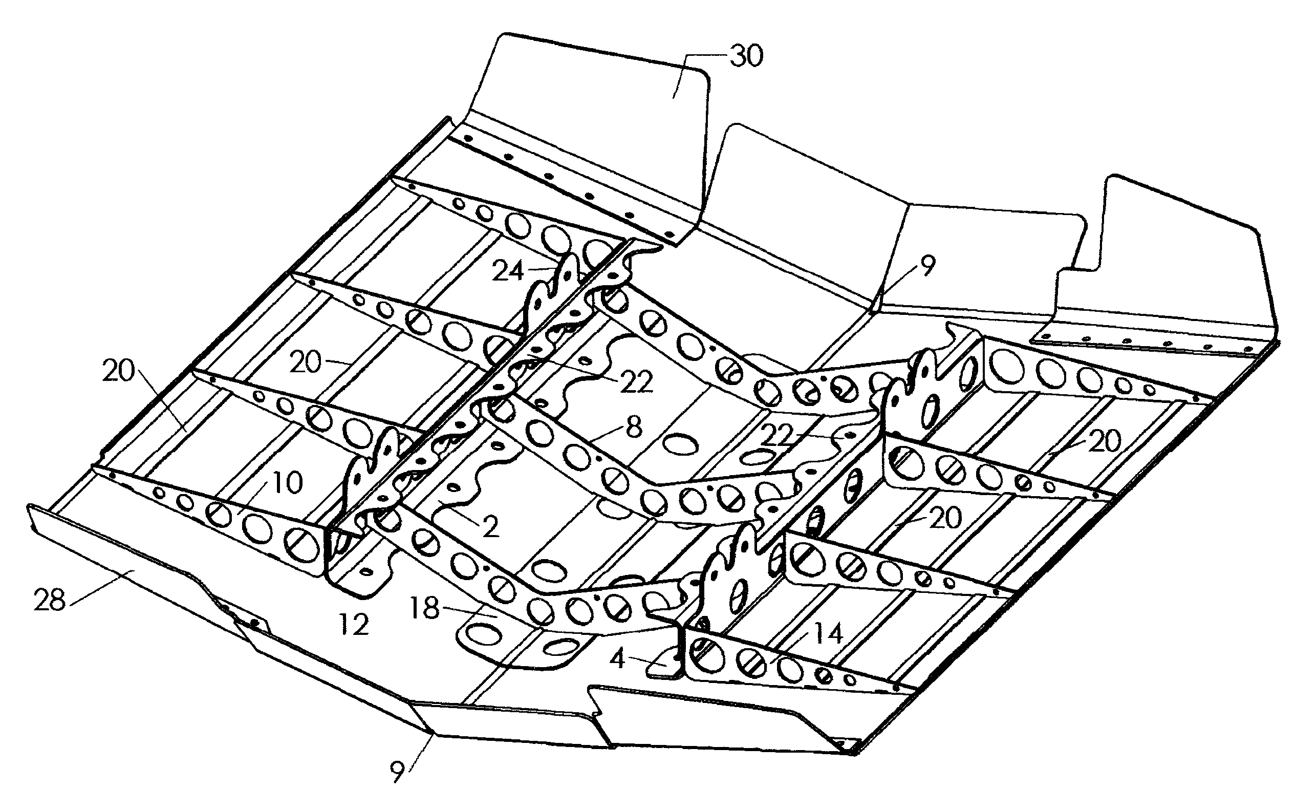
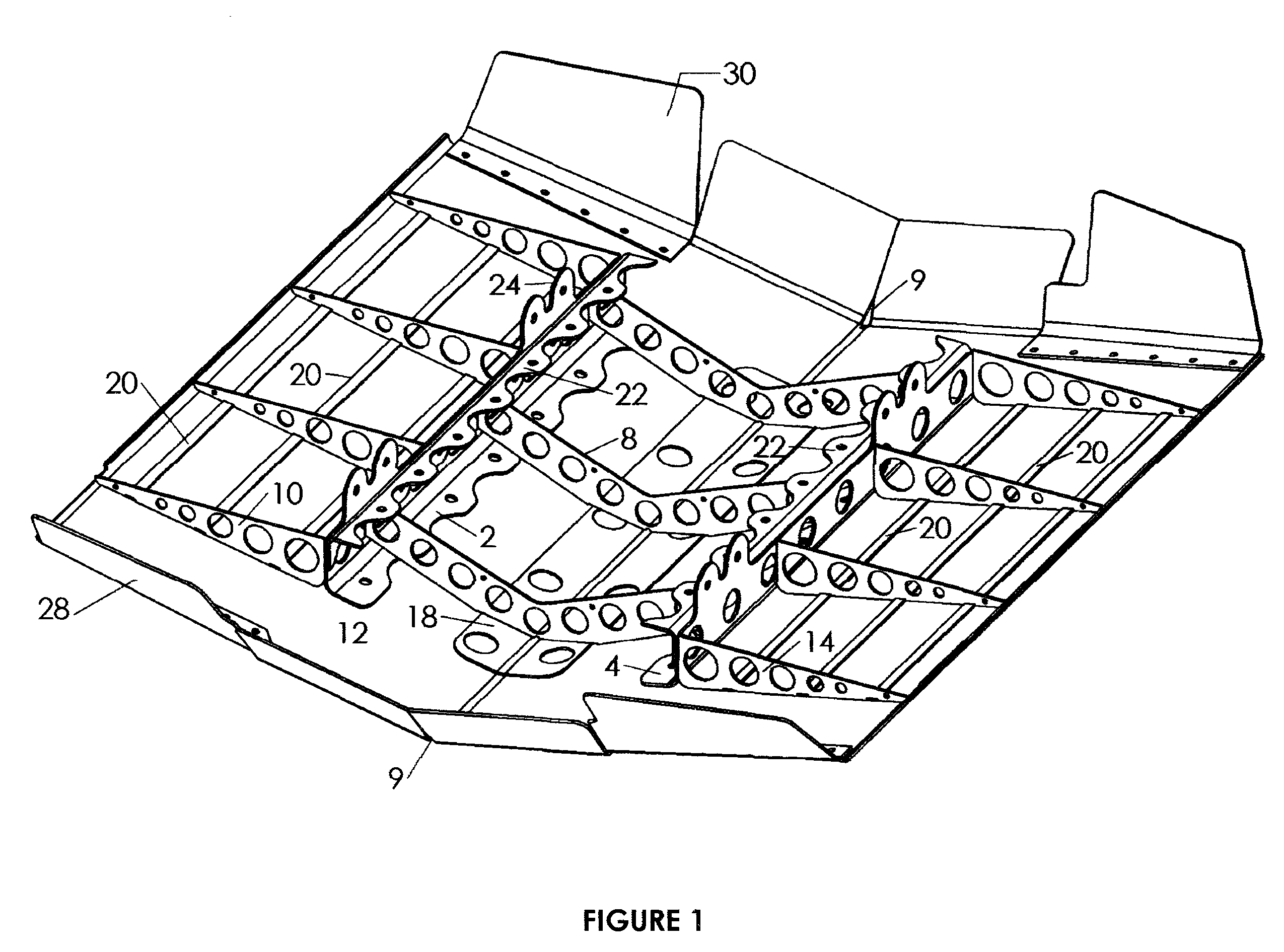
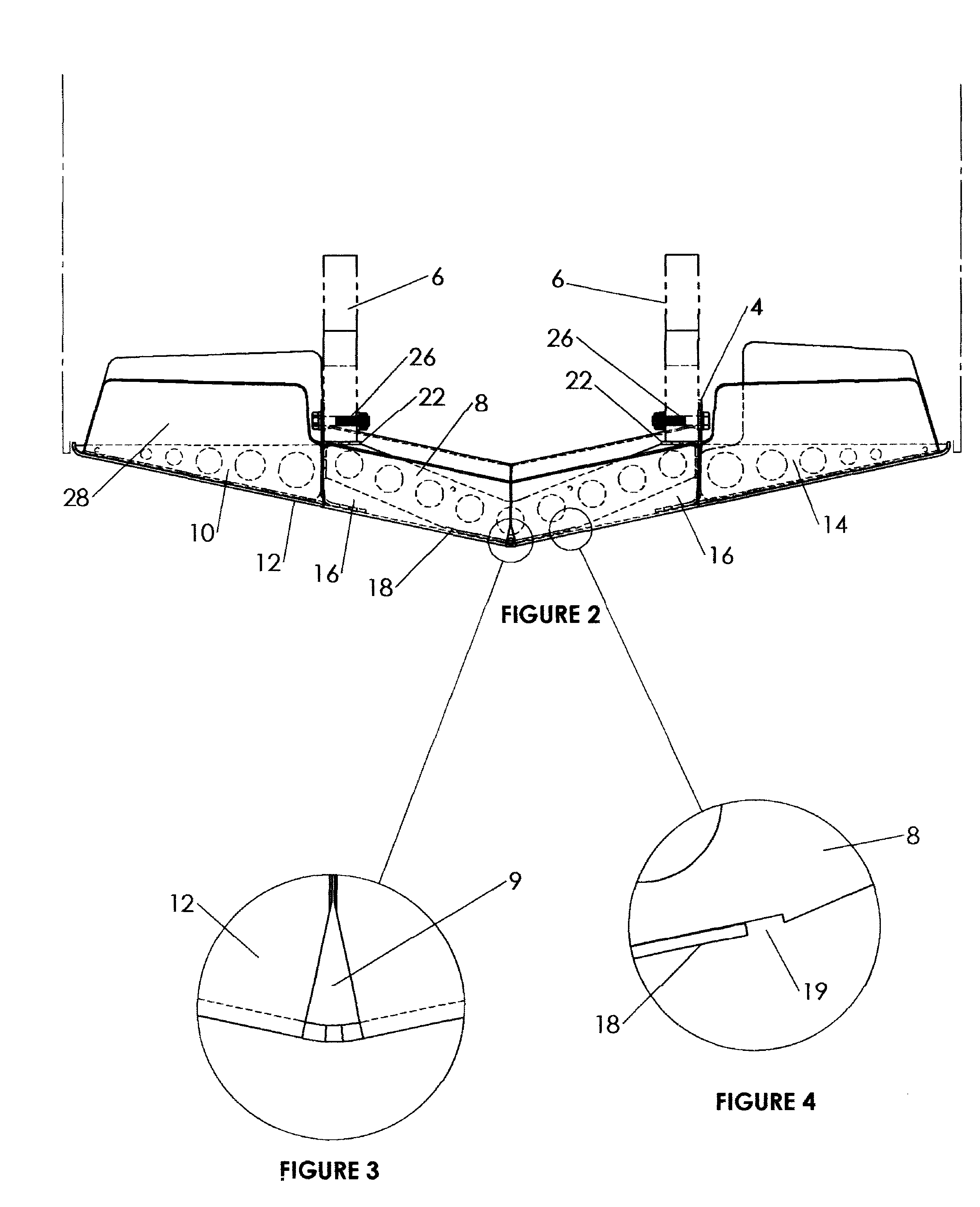
[0017]Turning now to the drawing figures, FIG. 1 shows the major elements of the protective hull for a vehicle according to an embodiment of the invention. As shown, the protective hull has upright supports, or members, that comprise a first longitudinal member 2 and a second longitudinal member 4. The longitudinal members are preferred to be generally parallel to each other. However, the longitudinal sides may be adapted to the geometry of the frame of the vehicle 6 to which the protective hull is to be mounted.

[0018]Disposed between the longitudinal first member and the second longitudinal member are a plurality of V-shaped support members 8. In a preferred embodiment, there are three V-shaped supports. It is preferred that at least three V-shaped supports are employed. However, additional supports or fewer supports, may be used depending upon the length of the vehicle to which the protective hull is to be mounted.

[0019]A plurality of supports 10 extends longitudinally from the u...


PUM


Abstract

A protective hull for a vehicle has a plate that covers at least a substantial portion of the underside of the vehicle. A plurality of supports extends laterally from longitudinal members, and a plurality of supports extends laterally from another longitudinal member. A plurality of V-shaped supports is disposed between the lateral supports. The supports have a plurality of voids therein. The voids do not have corners that could encourage tearing of the supports. Cells that are protected from puncture contain fire suppressant and are disposed over the supports.

Description

RELATED APPLICATIONS[0001]This application claims priority to, and the benefit of, provisional application Ser. No. 60 / 962,454 filed Aug. 16, 2007, and priority to, and the benefit of, provisional application Ser. No. 61 / 048,799 filed Apr. 29, 2008.FIELD OF THE INVENTION[0002]This invention relates to protective devices for vehicles.BACKGROUND OF THE INVENTION[0003]Vehicles operating in hazardous or dangerous conditions or circumstances may be subject to trauma from underneath the vehicle. Force may be rendered to the bottom of the vehicle from objects in the path of the vehicle that strike the underside of the vehicle. In the extreme, a vehicle may be subject to substantial force rendered by explosives. The source of the extreme force may be rendered by explosives such as bombs, or landmines that are intended to disable the vehicle as it traverses terrain.[0004]There is a need for a device that will protect the underside of the vehicles from trauma or force. The device should assis...

Claims


Application Information

Patent Timeline
IPC IPC(8): F41H5/013B60J11/00
CPCB62D25/2009F41H7/042
Inventor COX, TIMOTHY J.
Owner COX TIMOTHY J
Why Eureka
Try Eureka