Adjustable guide bar for woodworking table slot

a guide bar and slot technology, applied in the field of woodworking, can solve the problems of difficult adjustment of the set screws when the device is in the slot, unsatisfactory amount of positional uncertainty, and inability to provide a uniform fit of the guide bar

Active Publication Date: 2011-08-16
WANG HENRY
View PDF32 Cites 15 Cited by
  • Summary
  • Abstract
  • Description
  • Claims
  • Application Information

AI Technical Summary

Problems solved by technology

Any gap between the width of the guide bar and the width of the slot allows for some undesirable horizontal and angular movement of the guide bar and the guided work piece as it is moved through the cutting tool.
Such variation can create an unacceptable amount of positional uncertainty during woodworking operations.
Adjustment of the set screws prior to inserting the device into the slot requires a trial and error approach, or alternatively, adjustment of the set screws when the device is in the slot is difficult due to their horizontal orientation and limited access to the set screws.
However, localized deformation of the guide bar side walls does not provide a uniform fit of the guide bar along the full length of the guide bar within the slot.

Method used


Image

  • Adjustable guide bar for woodworking table slot
  • Adjustable guide bar for woodworking table slot
  • Adjustable guide bar for woodworking table slot

Examples


Embodiment Construction

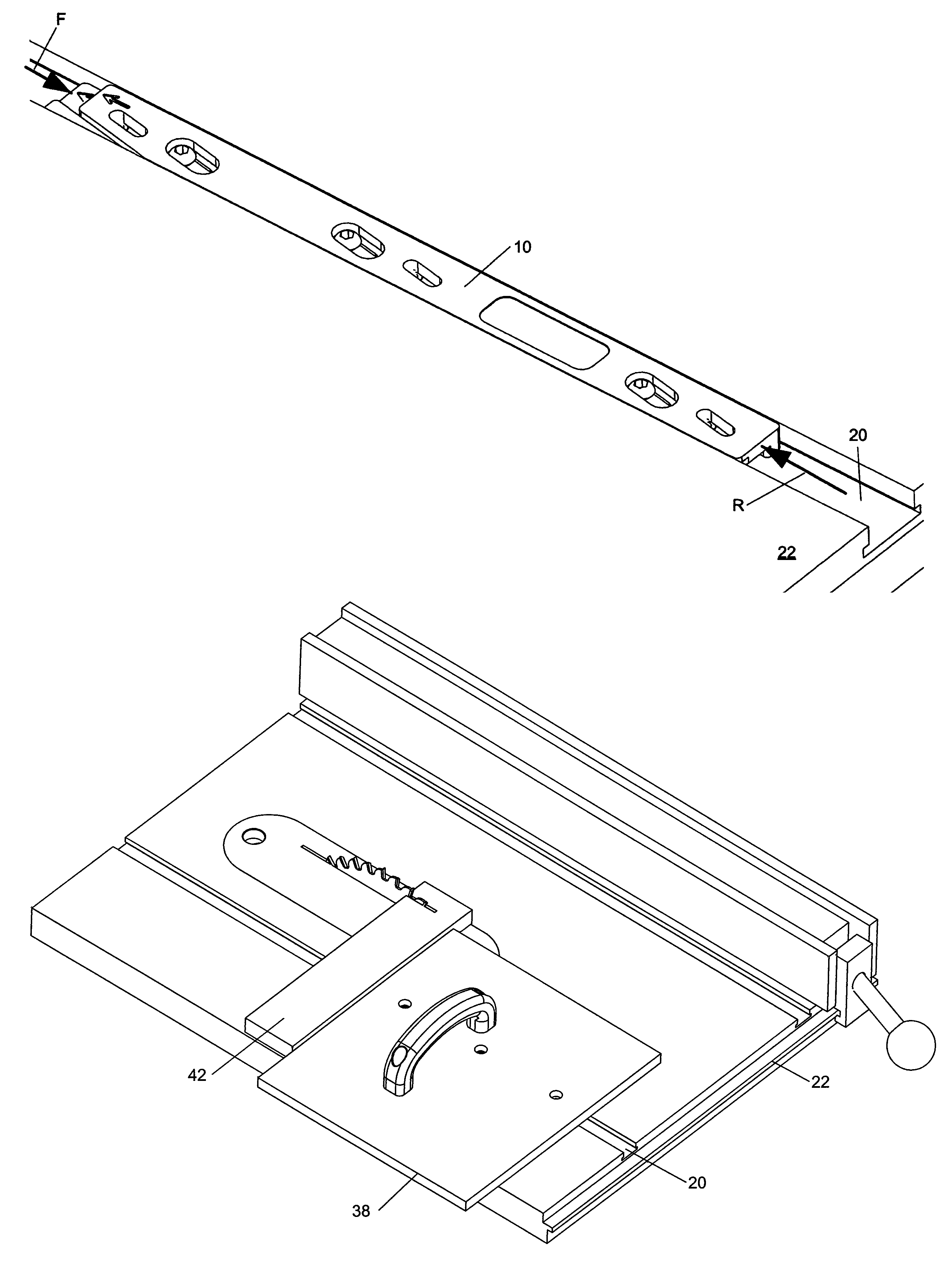
[0015]In response to the continued need in the woodworking industry for maintaining tight tolerances, and in particular for ensuring a snug, uniform fit of a guide bar within a woodworking table T-slot, the present inventor has developed an innovative guide bar design that provides a high degree of functionality in a rugged, shop-worthy device.

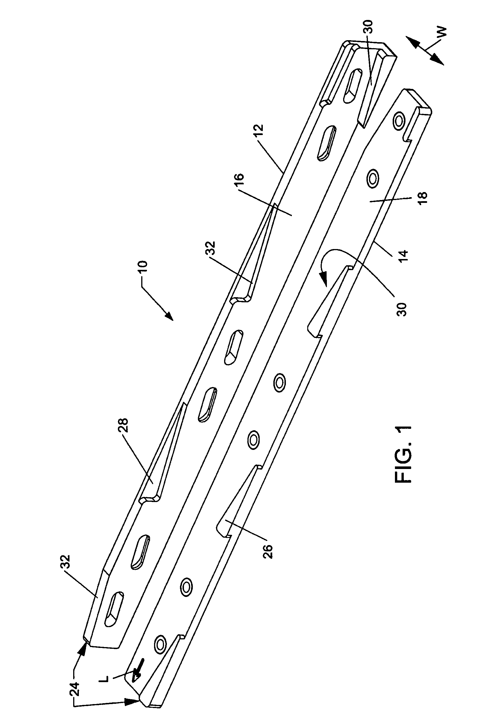
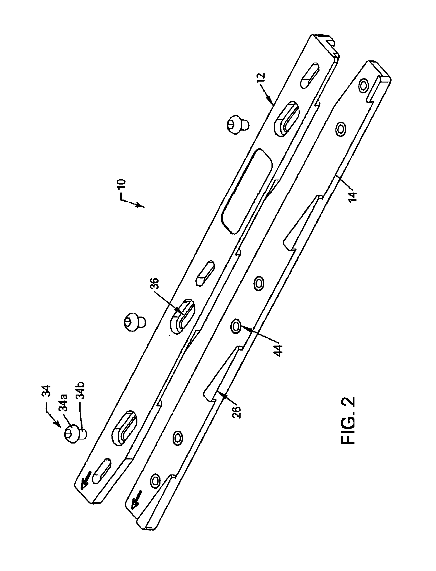
[0016]FIGS. 1-5 illustrate one embodiment of a guide bar assembly 10 in accordance with aspects of the present invention. The guide bar assembly 10 includes a top member 12 disposed on a bottom member 14 when assembled. FIG. 1 illustrates the underside surface 16 of the top member 12 and the topside surface 18 of the bottom member 14 which touch upon assembly, and FIG. 2 illustrates the two members 12, 14 in position ready for assembly. Each of the top member 12 and bottom member 14 has an elongated, generally rectangular, flat shape such that when joined together form an assembly 10 that will fit within a T-slot (or miter slot) of a woodworki...


PUM

PropertyMeasurementUnit
widthaaaaaaaaaa
angleaaaaaaaaaa
angleaaaaaaaaaa

Abstract

A guide bar assembly (10) for use in a T-slot (20) of a woodworking table (22). The assembly includes a top member (12) slidably disposed on a bottom member (14). The top and bottom members include cooperating pairs of wedge shapes (24) that cause a change in width (W) of the assembly in response to relative longitudinal (L) movement between the top and bottom members. Contacting angled side surfaces (30, 32) of the male and female wedge members (26, 28) provide area contact between the top and bottom members that functions to maintain the top and bottom members parallel during tightening of the fasteners (34) used to lock the assembly at a desired width.

Description

CROSS REFERENCE TO RELATED APPLICATIONS[0001]This application claims priority benefit of the 10 Oct. 2006 filing date of U.S. provisional patent application No. 60 / 828,828.FIELD OF THE INVENTION[0002]This invention relates generally to the field of woodworking and more particularly to a guide bar assembly for use within a slot on a woodworking table.BACKGROUND OF THE INVENTION[0003]High quality woodworking with safe operation requires the ability to maintain very close tolerances. Woodworking power tools such as table saws are known to include a straight groove or slot, known as a miter slot or a T-slot (referring to its common cross-sectional shape), for slidably receiving a guide bar. The guide bar moves within the T-slot to guide a work piece through a cutting tool, such as a saw blade, in a precise linear direction parallel to a desired cut line. Any gap between the width of the guide bar and the width of the slot allows for some undesirable horizontal and angular movement of th...

Claims


Application Information

Patent Timeline
Patent Type & Authority Patents(United States)
IPC IPC(8): B23D47/04B26D7/06
CPCB23Q1/262B23Q3/005B27B25/10Y10T83/6608Y10T83/6614Y10T83/6657Y10T83/727Y10T83/773
Inventor WANG, HENRY
Owner WANG HENRY
Why Eureka
Try Eureka