
Method and apparatus for spinal stabilization

a spinal stabilization and apparatus technology, applied in the field of medical devices, can solve the problems of high cost, long in-patient hospital stay, and increased pain of open procedures, and achieve the effects of improving the stability of the spinal column

Active Publication Date: 2011-08-16
DEPUY SYNTHES PROD INC
View PDF251 Cites 118 Cited by
  • Summary
  • Abstract
  • Description
  • Claims
  • Application Information

AI Technical Summary

Benefits of technology

[0010]Notwithstanding the variety of efforts in the prior art described above, these techniques are associated with a variety of disadvantages. In particular, these techniques typically involve an open surgical procedure, which results higher cost, lengthy in-patient hospital stays and the pain associated with open procedures.
[0011]Therefore, there remains a need for improved techniques and systems for stabilizing the spine. For example, the devices can be implantable through a minimally invasive procedure.
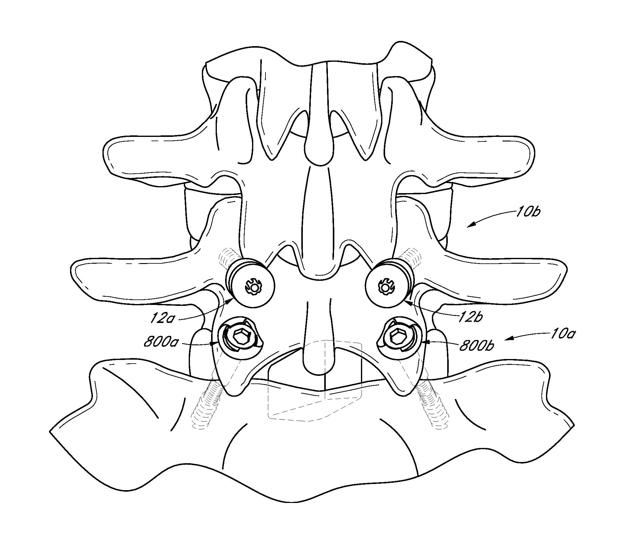
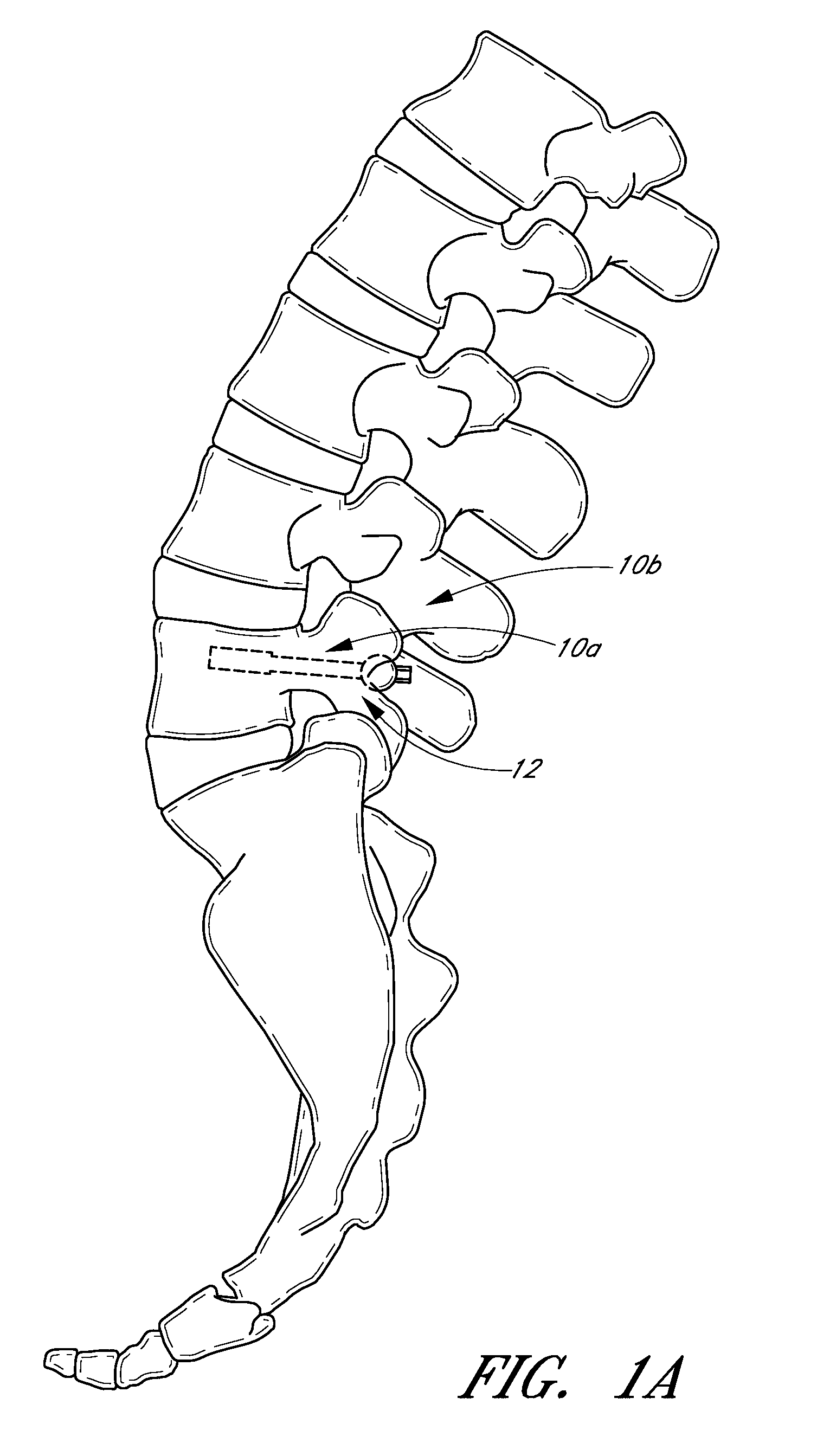
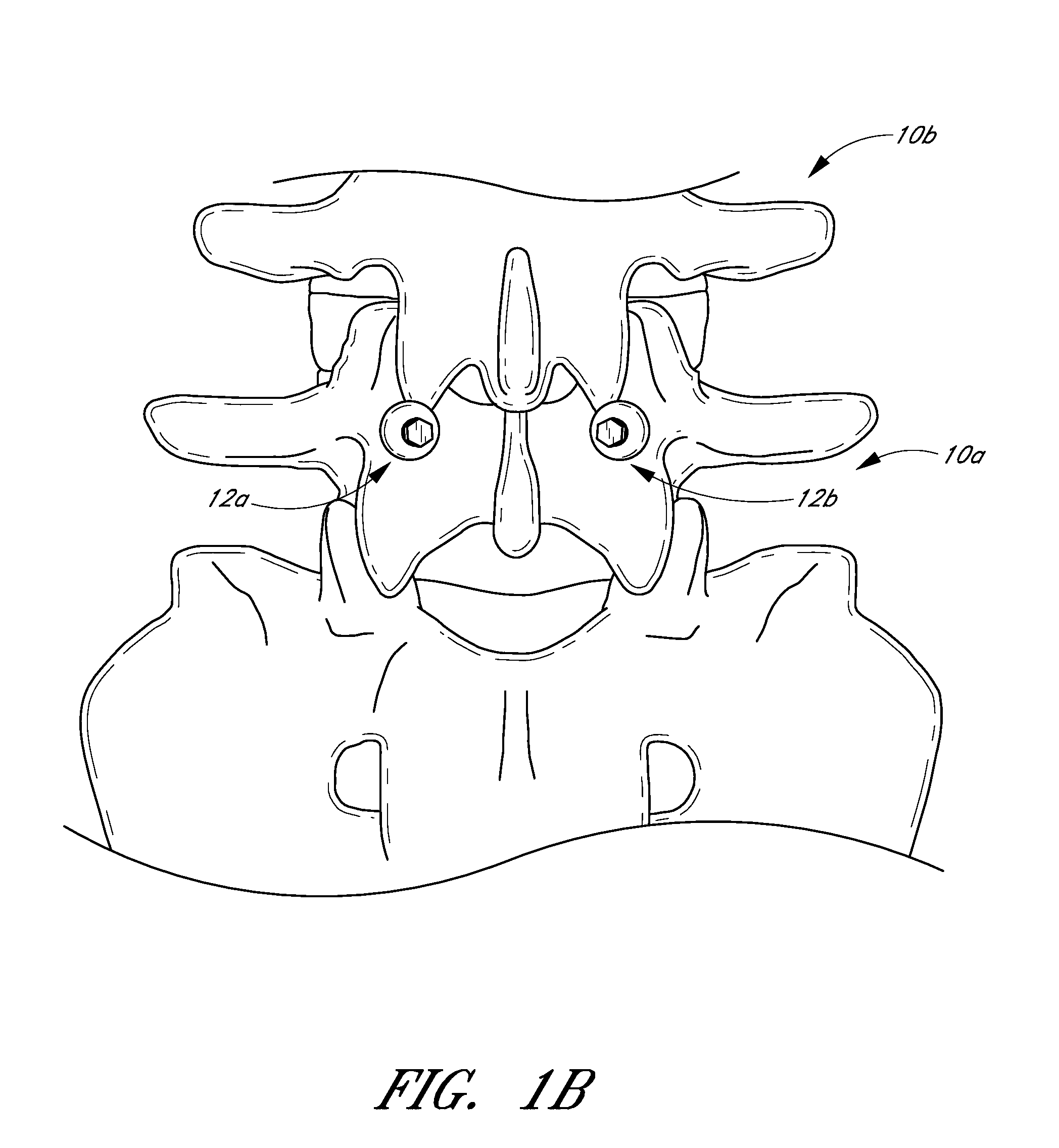
[0012]Accordingly, one embodiment of the present inventions comprises a method of limiting at least one degree of movement between a superior vertebral body, an intermediate vertebral body, and an inferior vertebral body of a patient. In accordance with an embodiment of the method, a distal end of a stabilization device can be advanced into a pedicle of the intermediate vertebral body. A proximal portion of the stabilization device can be positioned such that the proximal portion limits at least one degree of movement between a superior vertebral body and the intermediate vertebral body by contacting a surface of the superior vertebral body. Further, the method can further comprise advancing a distal end of a fixation device into a facet of the intermediate vertebral body and into a facet of the inferior vertebral body for stabilizing the intermediate vertebral body and the inferior vertebral body.
[0016]Another embodiment comprises a method of limiting at least one degree of movement between a superior vertebral body and an intermediate vertebral body of a patient. According to such an embodiment, a distal end of a first stabilization device can be advanced into a pedicle of the intermediate vertebral body. A proximal portion of the first stabilization device can be positioned such that the proximal portion abuts against a surface of an intermediate articular process of the superior adjacent vertebral body to limit at least one degree of movement between a superior vertebral body and an intermediate vertebral body. A distal end of a second stabilization device can be advanced into a pedicle of the intermediate vertebral body such that it is positioned with bilateral symmetry with respect to the first stabilization device. A proximal portion of the second stabilization device can be positioned such that the proximal portion abuts, with bilateral symmetry with respect to the first stabilization device, against a surface of a second intermediate articular process of the superior adjacent vertebral body to limit at least one degree of movement between the superior vertebral body and the intermediate vertebral body. Further, the method can also comprise advancing a distal end of a fixation device into a facet of the intermediate vertebral body and into a facet of the inferior vertebral body for stabilizing the intermediate vertebral body and the inferior vertebral body.
[0024]In such an embodiment, the orthopedic fixation device can comprise an elongate pin, at least one distal anchor, a proximal anchor, and an anti-rotational structure. The elongate pin can have a proximal end, a distal end, and a first retention structure. The at least one distal anchor can be carried by the elongate pin. The proximal anchor can be axially moveable with respect to the elongate pin and can comprise a split ring positioned within an annular recess formed within the proximal anchor. The split ring can have at least one gap formed between two ends and can be moveable between a first position and a second position. The second position can be located closer to the longitudinal axis of the elongate pin as compared to the first portion so as to engage the first retention structure and prevent proximal movement of the proximal anchor with respect to the elongated pin while the first position allows distal movement of the proximal anchor with respect to the pin. The anti-rotational structure can prevent rotation of the split ring about the longitudinal axis of the elongate pin.

Problems solved by technology

Additionally, the vertebrae and associated connective elements are subject to injuries, including fractures and torn ligaments and surgical manipulations, including laminectomies.
In particular, these techniques typically involve an open surgical procedure, which results higher cost, lengthy in-patient hospital stays and the pain associated with open procedures.

Method used


Image

  • Method and apparatus for spinal stabilization
  • Method and apparatus for spinal stabilization
  • Method and apparatus for spinal stabilization

Examples


Embodiment Construction

[0080]Although embodiments of the present inventions will be disclosed primarily in the context of a spinal stabilization procedure, the methods and structures disclosed herein are intended for application in any of a variety medical applications, as will be apparent to those of skill in the art in view of the disclosure herein. For example, certain features and aspects of bone stabilization device and techniques described herein may be applicable to proximal fractures of the femur and a wide variety of fractures and osteotomies, the hand, such as interphalangeal and metacarpophalangeal arthrodesis, transverse phalangeal and metacarpal fracture fixation, spiral phalangeal and metacarpal fracture fixation, oblique phalangeal and metacarpal fracture fixation, intercondylar phalangeal and metacarpal fracture fixation, phalangeal and metacarpal osteotomy fixation as well as others known in the art. See e.g., U.S. Pat. No. 6,511,481, which is hereby incorporated by reference herein. A wi...


PUM


Abstract

A method and apparatus of limiting at least one degree of movement between a superior vertebral body, an inferior vertebral body, and an intermediate vertebral body that is disposed between the superior and inferior vertebral bodies of a patient. The method can comprise: advancing a distal end of a stabilization device into a pedicle of the intermediate vertebral body; positioning a proximal portion of the stabilization device such that the proximal portion limits at least one degree of movement between the superior vertebral body and the intermediate vertebral body by contacting a surface of the superior vertebral body; and advancing a distal end of a fixation device into a facet of the intermediate vertebral body and into a facet or pedicle of the inferior vertebral body for stabilizing the intermediate vertebral body and the inferior vertebral body.

Description

CROSS-REFERENCE TO RELATED APPLICATIONS[0001]This application claims the benefit of U.S. Provisional Application No. 60 / 942,998, filed Jun. 8, 2007, the entirety of which is incorporated herein by reference.BACKGROUND[0002]1. Field of the Inventions[0003]The present inventions relate to medical devices and, more particularly, to methods and apparatuses for dynamic spinal stabilization.[0004]2. Description of the Related Art[0005]The human spine is a flexible weight bearing column formed from a plurality of bones called vertebrae. There are thirty three vertebrae, which can be grouped into one of five regions (cervical, thoracic, lumbar, sacral, and coccygeal). Moving down the spine, there are generally seven cervical vertebra, twelve thoracic vertebra, five lumbar vertebra, five sacral vertebra, and four coccygeal vertebra. The vertebra of the cervical, thoracic, and lumbar regions of the spine are typically separate throughout the life of an individual. In contrast, the vertebra of...

Claims


Application Information

Patent Timeline
Patent Type & Authority Patents(United States)
IPC IPC(8): A61B17/88
CPCA61B17/863A61B17/1671A61B17/7064A61B17/8891A61B17/1664A61B17/1686A61B17/862A61B17/864A61B17/8883A61B17/1682
Inventor CULBERT, BRAD S.
Owner DEPUY SYNTHES PROD INC
Learn More