
Hinge-link spinal correction device and method

a spinal correction and hinge-link technology, applied in the field of spinal deformation correction, can solve the problems of ineffective and risky methods and systems, prior art methods and systems, and the deformation of the spine subject to vcr, and achieve the effects of stabilizing the spine, and preventing compression, distraction, or translation of the spinal cord

Active Publication Date: 2020-09-24
TEXAS SCOTTISH RITE HOSPITAL FOR CHILDREN
View PDF0 Cites 2 Cited by
  • Summary
  • Abstract
  • Description
  • Claims
  • Application Information

AI Technical Summary

Benefits of technology

The patent describes a method for stabilizing a spine during spinal correction procedures. The method involves attaching a stabilizer assembly to the spine using spinal rods and a hinge. The hinge allows for coronal or sagittal freedom of movement. The stabilizer assembly includes stabilizing rods and monoaxial or polyaxial links that are connected to the rods. These links are movably coupled to the rods and can be locked in position to stabilize the spine. The method helps prevent compression, distraction, or translation of the spinal cord during spinal correction procedures. The stabilizer assembly can be attached to the rods to provide coronal or sagittal freedom of movement. The technical effect of the patent is to provide a reliable and effective method for stabilizing the spine during spinal correction procedures.

Problems solved by technology

Prior art method and systems are difficult and risky because they do not provide for fine control of the initial stabilization during the VCR, stabilization, manipulation, or the long-term fixing in place of the spine without risk of compression, distraction, or translation of the spinal cord.
Methods and systems for stabilization, manipulation, and fixation of a deformed spine subject to a VCR are ineffective and risky.

Method used


Image

  • Hinge-link spinal correction device and method
  • Hinge-link spinal correction device and method
  • Hinge-link spinal correction device and method

Examples


Embodiment Construction

[0038]Illustrative embodiments of the system of the present application are described below. In the interest of clarity, not all features of an actual implementation are described in this specification. It will of course be appreciated that in the development of any such actual embodiment, numerous implementation-specific decisions must be made to achieve the developer's specific goals, such as compliance with system-related and business-related constraints, which will vary from one implementation to another. Moreover, it will be appreciated that such a development effort might be complex and time-consuming but would nevertheless be a routine undertaking for those of ordinary skill in the art having the benefit of this disclosure.

[0039]In the specification, reference may be made to the spatial relationships between various components and to the spatial orientation of various aspects of components as the devices are depicted in the attached drawings. However, as will be recognized by...


PUM


Abstract

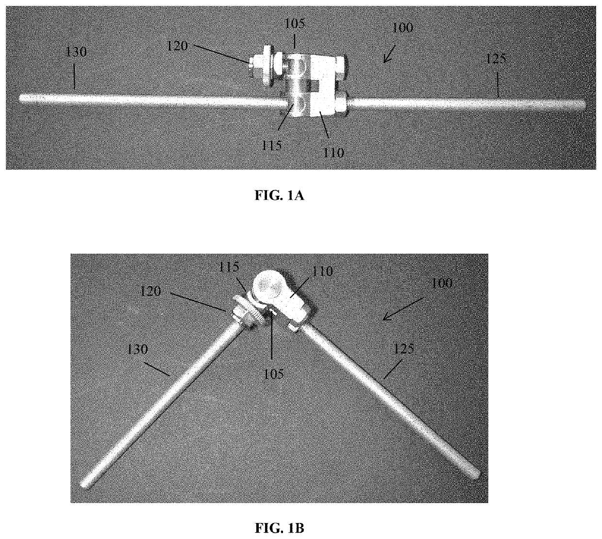
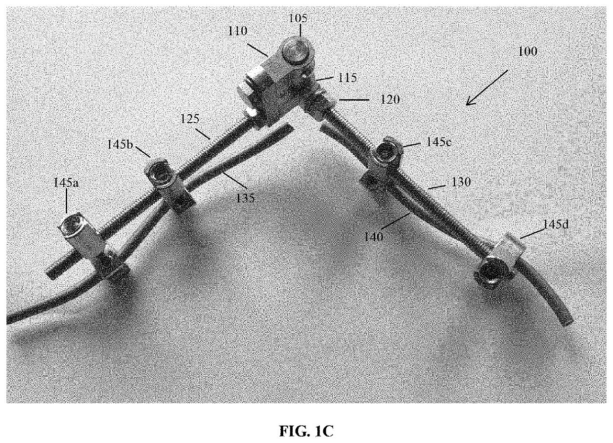
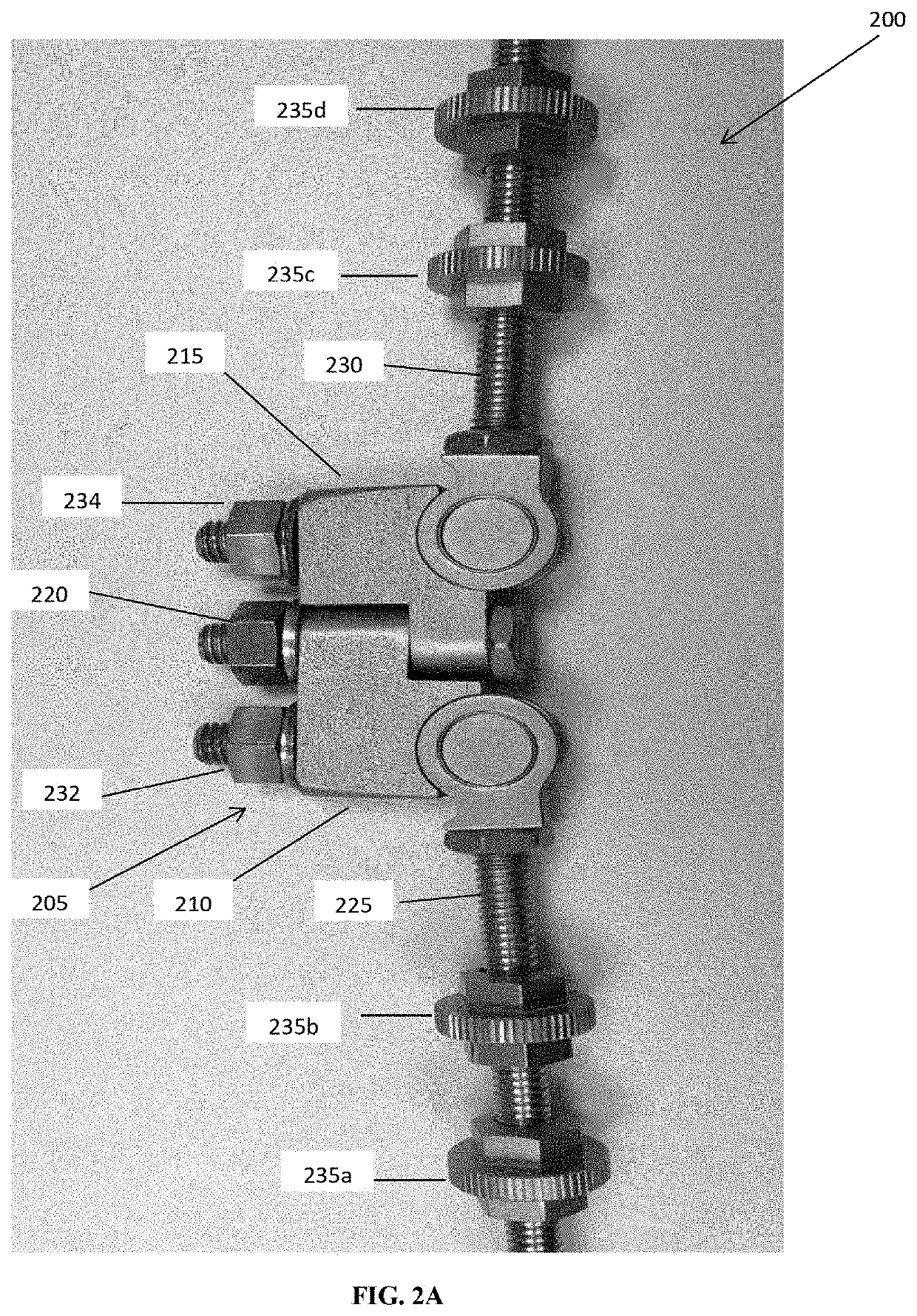
A device for spinal correction includes a stabilizer assembly including a hinge including a first rod-bearing leaf; a second rod-bearing leaf rotatably coupled to the first rod-bearing leaf to provide coronal or sagittal freedom of movement, or both, of the stabilizer assembly; a locking mechanism to lock the first and second rod-bearing leaves at a desired angle; a first stabilizing rod coupled to the first rod-bearing leaf; a second stabilizing rod coupled to the second rod-bearing leaf; and a plurality of monoaxial or polyaxial links, wherein each monoaxial or polyaxial link is movably coupled to the first or second stabilizing rod and is movably couplable to a first spinal rod or a second spinal rod fixed to the spine; wherein the stabilizer assembly is couplable to the first or second spinal rod to stabilize the spine to prevent compression, distraction, or translation of the spinal cord during a spinal correction.

Description

CROSS-REFERENCE TO RELATED APPLICATIONS[0001]This application is a non-provisional patent application of and claims priority to U.S. provisional patent application Ser. No. 62 / 822,345 filed on Mar. 22, 2019 and entitled “Hinge-Link Spinal Correction Device and Method,” the contents of which are hereby incorporated by reference in their entirety.STATEMENT OF FEDERALLY FUNDED RESEARCH[0002]Not applicable.TECHNICAL FIELD OF THE INVENTION[0003]The present invention relates in general to the treatment of spinal deformations. In particular, the present invention relates to the correction of spinal deformation in which a vertebral column resection is performed.BACKGROUND OF THE INVENTION[0004]Without limiting the scope of the invention, its background is described in connection with the use of a device to stabilize and manipulate a deformed spine on which a vertebral column resection (VCR) or spinal correction is being or has been performed into a desired position and then fixing the spine...

Claims


Application Information

Patent Timeline
Patent Type & Authority Applications(United States)
IPC IPC(8): A61B17/70
CPCA61B17/7023A61B17/7049A61B17/7034A61B17/7008A61B17/705A61B17/7077
Inventor ZHANG, HONGROSS, JR., JOHN DAVIDSUCATO, DANIEL J.
Owner TEXAS SCOTTISH RITE HOSPITAL FOR CHILDREN
Learn More