Intra compression of pixel blocks using predicted mean

a prediction and compression technology, applied in the field of multimedia data compression methods and apparatuses, can solve the problems of increasing the cost and affecting the efficiency of encoding/decoding video frames

Inactive Publication Date: 2005-11-24
MICROSOFT TECH LICENSING LLC
View PDF49 Cites 34 Cited by
  • Summary
  • Abstract
  • Description
  • Claims
  • Application Information

AI Technical Summary

Benefits of technology

[0028] What is needed is an apparatus and method that improves the efficiency of encoding / decoding video frames while maintaining a desired bit rate for a given resolution. More specifically, what is needed is an apparatus and method that incorporates several forms of motion estimation, and selects the best form for each block of data to be encoded.
[0029] Accordingly, it is a feature of the present invention to provide a method to encode a video frame that is transmitted over a communications medium. The method includes: 1) obtaining a video frame; 2) separating the frame into blocks; 3) encoding a plurality of blocks using inter compression; 4) encoding the plurality of blocks using predictive intra compression; and 5) selecting better block compression between the inter and predictive intra compression; wherein the steps of encoding the plurality of blocks is performed on a block by block basis, to provide optimum compression of the video frame for a given bit rate.

Problems solved by technology

This was geographically cumbersome.
But, for the most part, viewers of television can only view images that are scheduled for transmission, rather than selecting images at will.
As is typically of computer equipment and services, higher performance means more cost.
With present technology, even very expensive storage systems, and high speed networks would be overwhelmed if alternatives were not provided.
However, as frames are combined into moving pictures, the amount of data that must be transmitted is still significant.
For full motion video, including multicast video, teleconferencing, and interactive video, compressing each video frame separately is not sufficient, because of the large number of frames in even a short video sequence.
As the complexity that is associated with compression and decompression increases, the efficiency with which video frames may be encoded and decoded drops.
Therefore, a tradeoff is generally made between obtaining a particular compression ratio, and obtaining a satisfactory bit rate of transfer.
If a high compression ratio takes too long to decode, viewed images will appear choppy or disjunct.
If an inadequate bit rate is obtained, a viewer will be kept waiting for the image, or the image will replay in slow motion.

Method used


Image

  • Intra compression of pixel blocks using predicted mean
  • Intra compression of pixel blocks using predicted mean
  • Intra compression of pixel blocks using predicted mean

Examples


Embodiment Construction

[0054] The present invention provides a complex but efficient method and apparatus for compressing / decompressing video information that is distributed over a computer network. However, before discussing the detailed portions of the invention, a general overview will be provided.

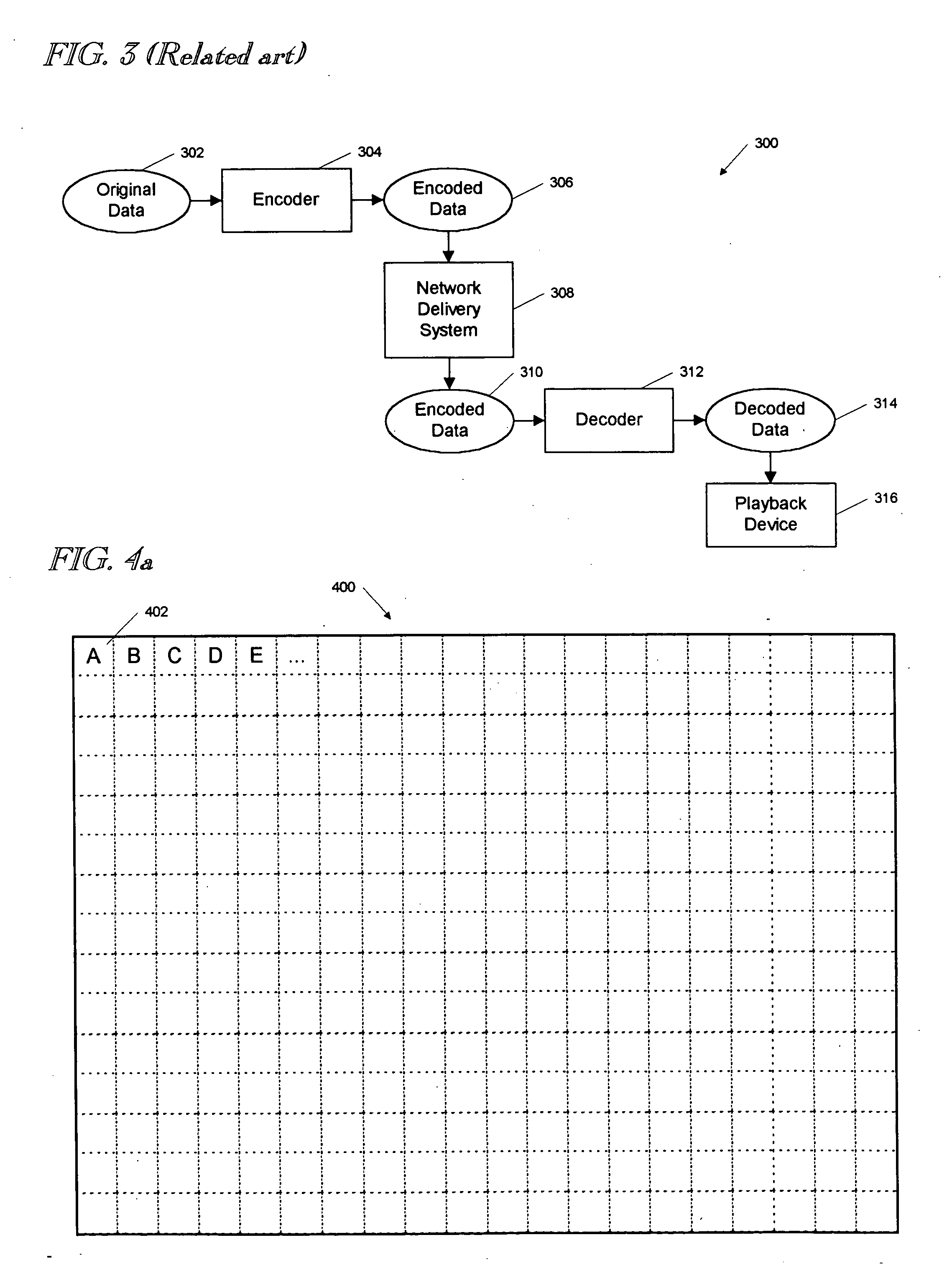
[0055] Referring to FIG. 3, a block diagram 300 of a data encoder / decoder system is shown. The system 300 includes original data 302, or data that is generally unencoded. The original data 302 may be a sequence of video frames, as described above, having a resolution of 320×240 pixels, and a color palette of 256 colors. The original data 302 is provided to an encoder 304 that encodes or compresses the data 302, and provides encoded data 306 as output. Although any suitable compression method may be used compress the original data 302, a preferred method includes that described in U.S. patent application Ser. No. 08 / 623,299 referenced above.

[0056] The encoded data 306 is provided to a network delivery system...


PUM


Abstract

An apparatus and method for encoding video frames is provided. The video frames are divided into blocks for encoding. Encoding of the video blocks utilizes motion detection, motion estimation and adaptive compression, to obtain the desired compression for a particular bit rate. Adaptive compression includes intra compression (without regard to other frames) and inter compression (with regard to other frames). Intra compression, inter compression with motion detection, and inter compression with motion estimation are performed on a block by block basis, as needed. Segmentation is provided to compare encoding of a block with encoding of its sub-blocks, and to select the best block size for encoding.

Description

CROSS-REFERENCE TO RELATED APPLICATIONS [0001] This application continuation-in-part of U.S. patent application Ser. No. 08 / 623,299, filed Mar. 28, 1996, entitled “TABLE-BASED LOW-LEVEL IMAGE CLASSIFICATION SYSTEM”; and is related to co-pending U.S. patent application Ser. No. 08 / 625,650, filed Mar. 29, 1996, entitled “TABLE-BASED COMPRESSION WITH EMBEDDING CODING”; Ser. No. 08 / 714,447, filed Sep. 16, 1996, entitled “MULTIMEDIA COMPRESSION SYSTEM WITH ADDITIVE TEMPORAL LAYERS”; Ser. No. ______ (Docket No. VXT:701) entitled “METHOD AND APPARATUS FOR IMPLEMENTING MOTION DETECTION IN VIDEO COMPRESSION,”; Ser. No. ______ (Docket No. VXT:702) entitled “DIGITAL VIDEO SIGNAL ENCODER AND E CODING METHOD,”; Ser. No. ______ (Docket No. VXT703) entitled “PRODUCTION OF A VIDEO STREAM WITH SYNCHRONIZED ANNOTATIONS OVER A COMPUTER NETWORK”; Ser. No. ______ (Docket No. VXT:704) e titled “METHODS AND APPARATUS FOR IMPLEMENTING CONTROL FUNCTIONS IN A STREAMED VIDEO DISPLAY SYSTEM”; Ser. No. ______ (...

Claims


Application Information

Patent Timeline
Patent Type & Authority Applications(United States)
IPC IPC(8): G06K9/36G06T9/00G10L19/00H03M7/30H04N7/26H04N7/30H04N7/36H04N7/50H04N19/593H04N19/94
CPCH04N19/119H04N19/593H04N19/51H04N19/147H04N19/10H04N19/115H04N19/146H04N19/19H04N19/48H04N19/60H04N19/61H04N19/63H04N19/90H04N19/94H04N19/96H03M7/3082
Inventor WANG, ALBERT S.MEHROTRA, SANJEEV
Owner MICROSOFT TECH LICENSING LLC
Why Eureka
Try Eureka