Spinal stabilization system

a stabilization system and spine technology, applied in the field of orthopedic surgery system, can solve the problems of reducing nerve function, affecting the recovery of patients, and affecting the recovery of patients, and achieve the effect of reducing the diameter of the first slo

Active Publication Date: 2017-06-13
K2M
View PDF12 Cites 5 Cited by
  • Summary
  • Abstract
  • Description
  • Claims
  • Application Information

AI Technical Summary

Benefits of technology

[0014]In another embodiment of the present disclosure, the spinal stabilization system further includes a second spinal rod and a second slot on the plate, the second slot transverse to the axis extending through the throughhole. A diameter of the second slot decreases when the throughhole transitions towards the expanded configuration, thereby securing the second spinal rod in the second slot of the plate.
[0015]In another aspect of the present disclosure, a method of stabilizing a spine includes, providing a first spinal rod, a bone screw, a plate, and a set screw. The bone screw includes a head portion and a threaded distal portion extending therefrom, the head portion transitionable between a first diameter and a second diameter. The plate includes a throughhole and a first slot, the first slot transverse to an axis extending through the throughhole, and the throughhole is transitionable between a collapsed configuration and an expanded configuration. The set screw includes a head portion adapted to receive a driving tool and a distal portion extending therefrom, the distal portion having threads for engaging a threaded lumen of the bone screw. The head portion of the bone screw is insertable into the throughhole such that rotation of the set screw relative to the bone screw advances the set screw and transitions the head portion of the bone screw towards the second diameter, and transitions the throughhole towards the expanded configuration, such that a diameter of the first slot decreases securing the first spinal rod into the first slot. The method further includes implanting the bone screw into a bone of a patient, positioning the head portion of the bone screw into the throughhole of the plate, adjusting the contour of the first spinal rod as need, and placing the first spinal rod into the first slot. The method also includes engaging the threads of the set screw to the threaded lumen of the bone screw, and advancing the set screw with respect to the bone screw with a driving tool such that the diameter of the first slot is reduced.

Problems solved by technology

Persons suffering from any of the above conditions typically experience extreme or debilitating pain and often times diminished nerve function.
These conditions and their treatments can be further complicated if the patient is suffering from osteoporosis or bone tissue thinning and loss of bone density.
However, due to injury, degradation, disease or the like, these discs can rupture, degenerate and / or protrude to such a degree that the intervertebral space between adjacent vertebrae collapses as the disc loses at least a part of its support function.
This can cause impingement of the nerve roots and severe pain.
However, as in the case of all spinal corrective surgery, a significant amount of instrumentation may still be required to perform the bone on bone technique.
The process of properly inserting the spinal rod into the receiving slot of a bone screw and then securing that connecting rod in place can often require that the clinician use a number of instruments and expend a great deal of time and effort.
This instrumentation will remain permanently attached to the patient's spinal column throughout the patient's lifetime posing potential risks to the patient's long term health.

Method used


Image

  • Spinal stabilization system
  • Spinal stabilization system
  • Spinal stabilization system

Examples


Embodiment Construction

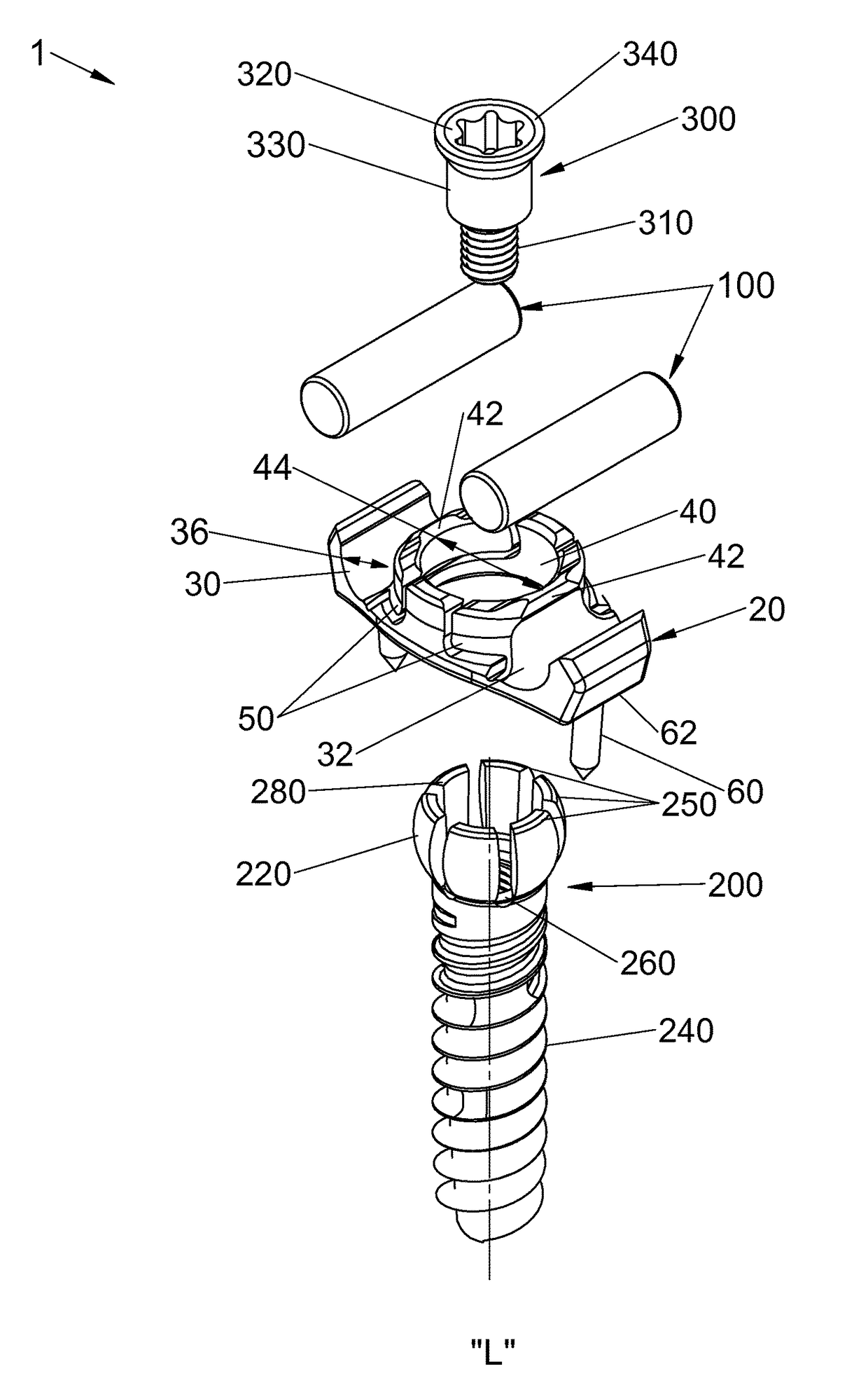
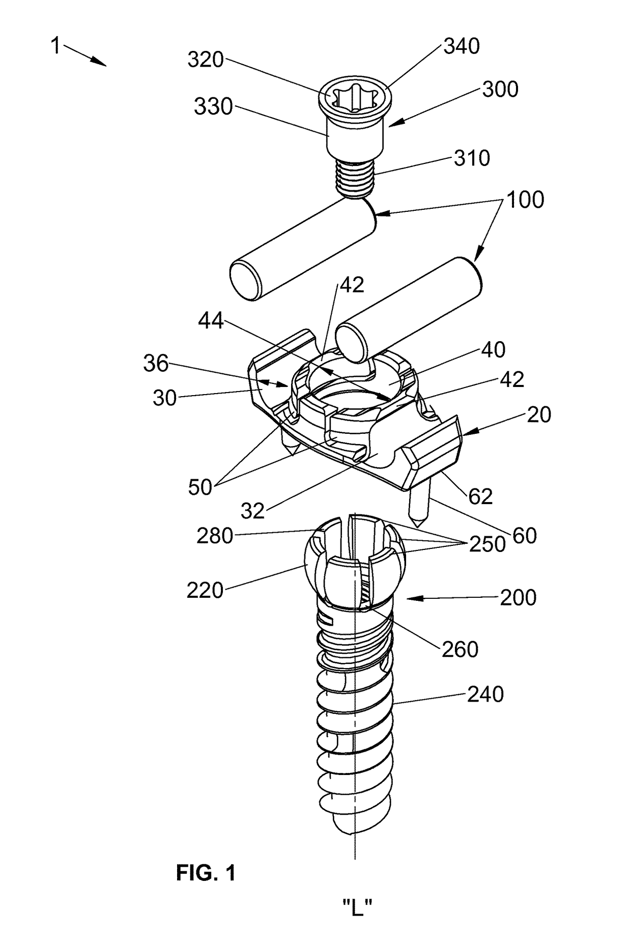
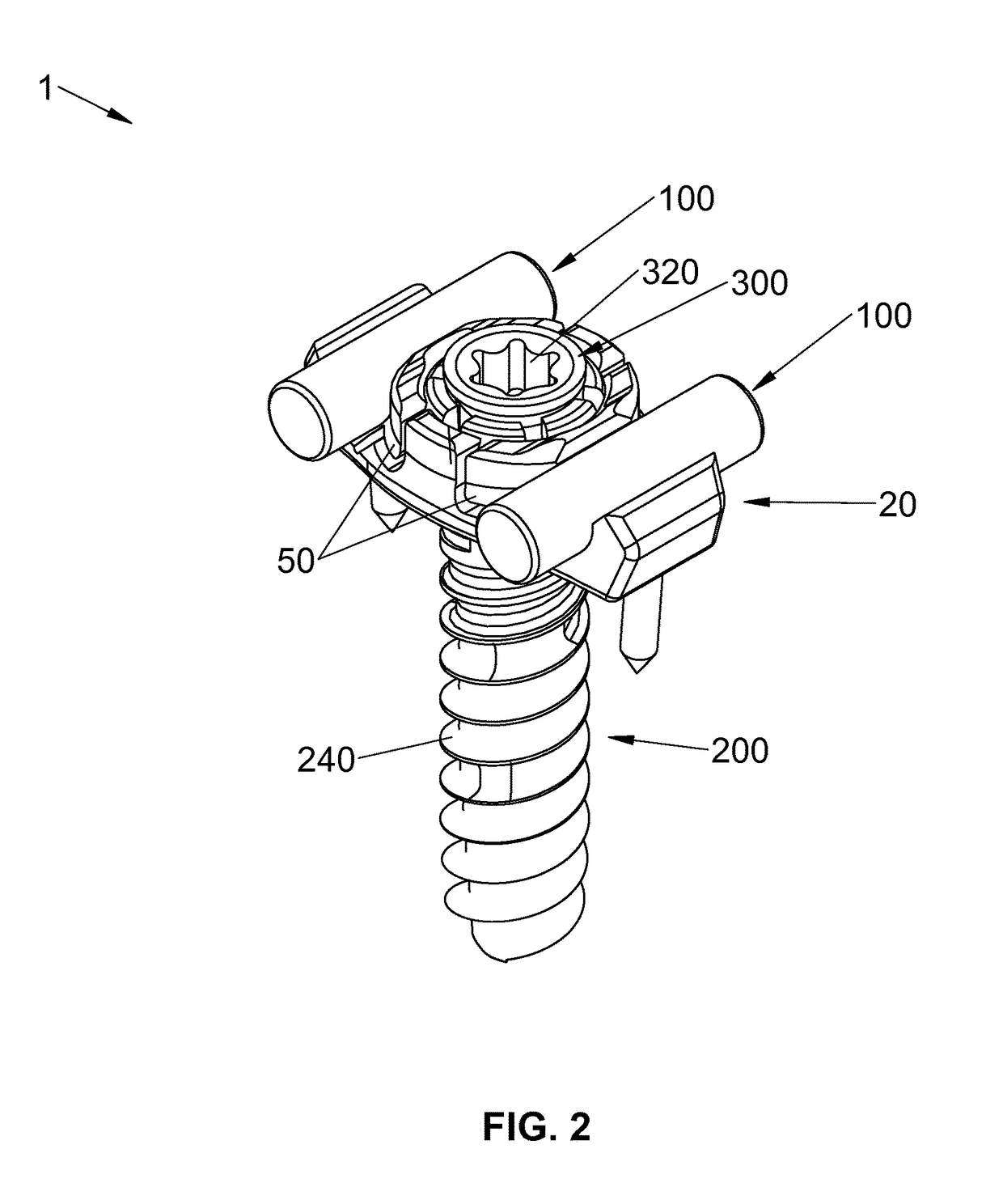
[0034]Embodiments of the present disclosure are now described in detail with reference to the drawings in which like reference numerals designate identical or corresponding elements in each of the several views. As is understood in the art, the term “clinician” refers to a doctor, a nurse, or any other care provider and may include support personnel. Throughout this description, the term “proximal” will refer to the portion of the apparatus or component thereof that is closer to the clinician and the term “distal” will refer to the portion of the apparatus or component thereof that is farther from the clinician. In addition, the term “cephalad” is used in this application to indicate a direction toward a patient's head, whereas the term “caudad” indicates a direction toward the patient's feet. Further still, for the purposes of this application, the term “lateral” indicates a direction toward a side of the body of the patient, i.e., away from the middle of the body of the patient, w...


PUM


Abstract

A spinal stabilization system includes a spinal rod, a plate, a set screw, and a bone screw. The plate includes a throughhole transitionable between a collapsed and expanded configuration, and a first slot adapted to receive a spinal rod therein. The set screw includes a distal portion having threads to engage with a threaded lumen of a bone screw, and the bone screw including a head portion transitionable between a first diameter and a second diameter. The head of the bone screw insertable into the throughhole and cooperatively transitions between the first diameter and the collapsed configuration to the second diameter and expanded configuration, respectively, as the set screw advances with respect to the bone screw to lock the spinal rod into the slot of the plate in the second diameter and expanded configuration.

Description

CROSS-REFERENCE TO RELATED APPLICATIONS[0001]The present application claims the benefit of U.S. Provisional Application Ser. No. 61 / 930,704, which was filed on Jan. 23, 2014, the entire contents of which are incorporated herein by reference.BACKGROUND[0002]Technical Field[0003]The present disclosure relates to an orthopedic surgery system for stabilizing and fixing the bones and joints of the body. Particularly, the present disclosure relates to a spinal stabilization system including a spinal rod, bone screws, set screws, and plates. Alternatively, the spinal stabilization system may include bone screws, threaded nuts, and a plate.[0004]Description of Related Art[0005]The spinal column is a complex system of bones and connective tissues that provides support for the human body and protection for the spinal cord and nerves. The human spine is comprised of thirty-three vertebrae at birth and twenty-four as a mature adult. Between each pair of vertebrae is an intervertebral disc, whic...

Claims


Application Information

Patent Timeline
Patent Type & Authority Patents(United States)
IPC IPC(8): A61B17/70A61B17/80
CPCA61B17/7001A61B17/7007A61B17/7032A61B17/7037A61B17/7041A61B17/7044A61B17/809
Inventor GAINES, ROBERTMIN, KANMOORE, BRANDON
Owner K2M
Why Eureka
Try Eureka