
Cure through laminate veneer applicator with cure light

a technology of laminate veneer and applicator, which is applied in the field of dentistry, can solve the problems of lack of cured resin, a myriad of challenging steps in the placement process, and a myriad of challenging steps

Active Publication Date: 2011-08-23
VISCOMI BRIAN D
View PDF18 Cites 19 Cited by
  • Summary
  • Abstract
  • Description
  • Claims
  • Application Information

AI Technical Summary

Benefits of technology

Facilitates precise, one-handed placement and curing of dental veneers, reducing the risk of slippage and incomplete curing, while minimizing the need for multiple instruments and hand position changes, ensuring comprehensive resin curing and reducing the risk of veneer fracture.

Problems solved by technology

The placement process presents with a myriad of challenging steps.
This is due to the veneer's innate fragility and size.
Wearing the required latex gloves adds more ergonomic difficulties to an already challenging step.
Slippage, mal-placement, and over expression of bonding agents, are just some of the untoward complications which can result from this.
Present placement systems, because of their structural design, present with an opaque central attachment apparatus which prevents the transfer of the light curing medium, with a subsequent lack of cured resin in the critical central portion of the veneer.
This opacity does not allow for light transference and hence leaves the critical central portion of the veneer uncured with the initial light application.
These tabs plus their attachment tip are opaque in nature and serve to prevent light transference to the critical central portion of the veneer thus subjecting the veneering process to potential complications by requiring a change in hand positioning, and an exchange of instruments.
The instrument head and the double-sided foam pad engage the veneer's central portion, and being opaque in nature serve to prevent light transference to the critical central portion of the veneer opaque by nature and therefore interfere with the transfer of a light source and subject the veneering process to potential complications by requiring a change in hand positioning, and an exchange of instruments.

Method used


Image

  • Cure through laminate veneer applicator with cure light
  • Cure through laminate veneer applicator with cure light
  • Cure through laminate veneer applicator with cure light

Examples


Embodiment Construction

FIGS. 1A to 3B—Preferred Embodiment

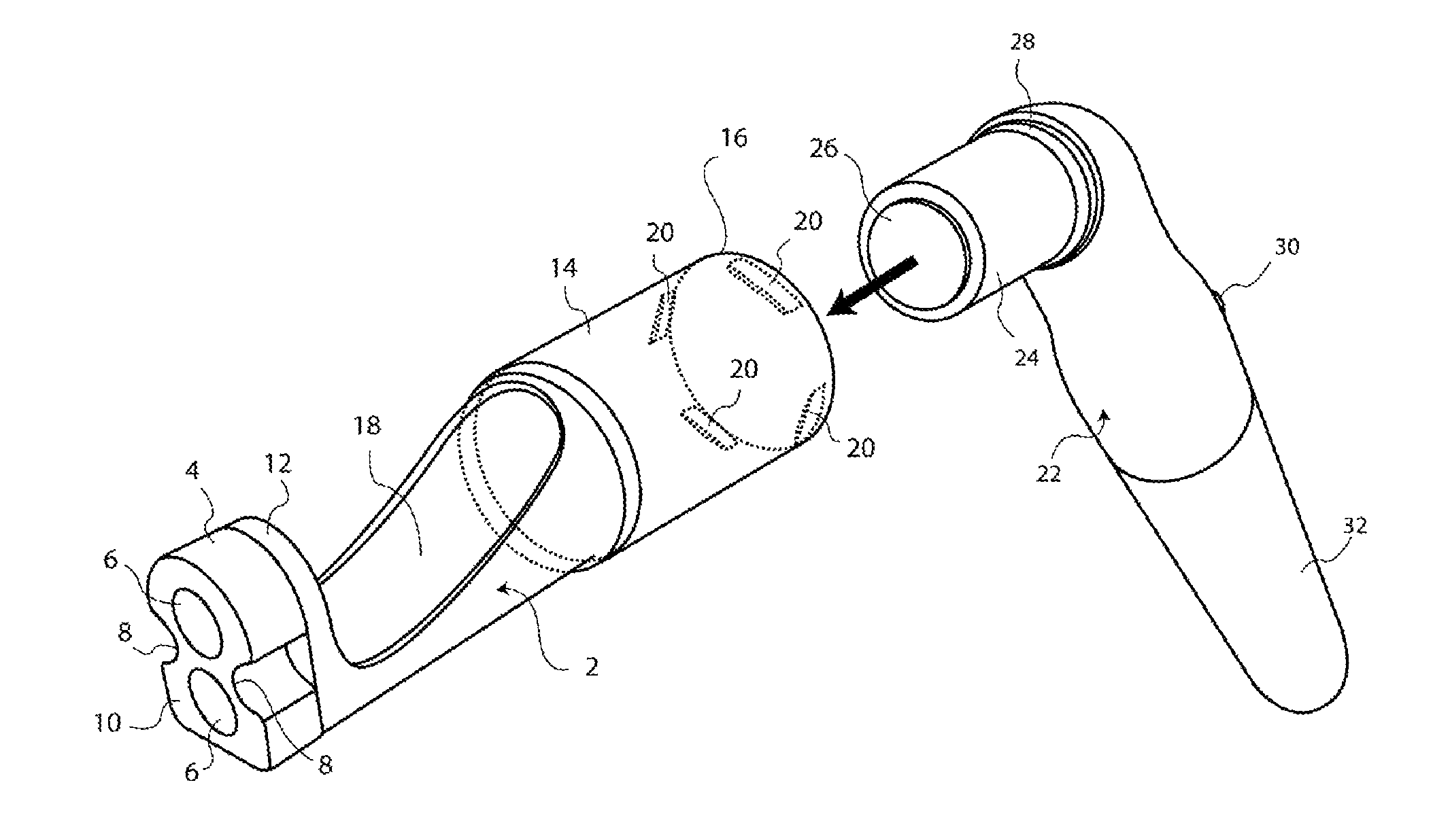
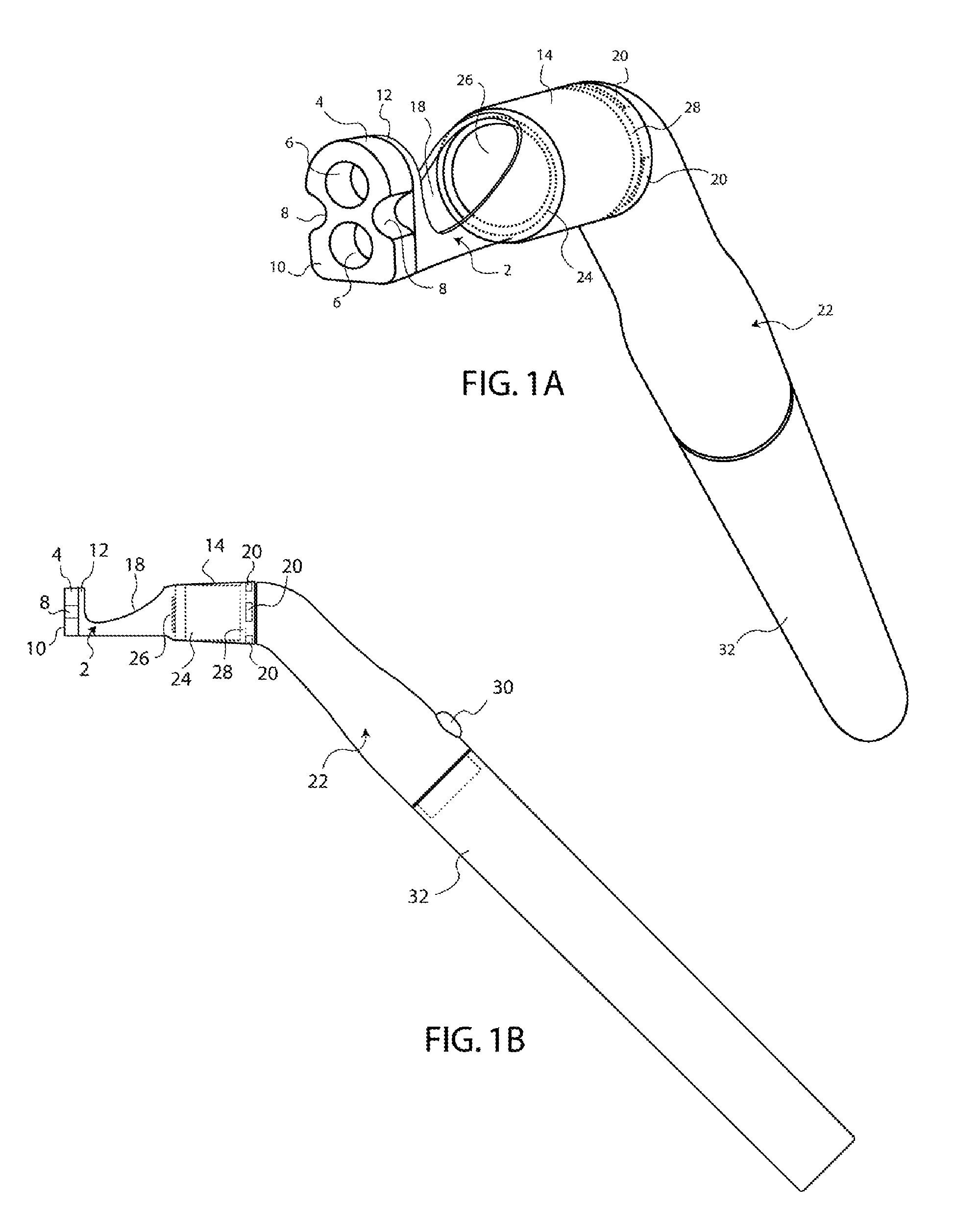
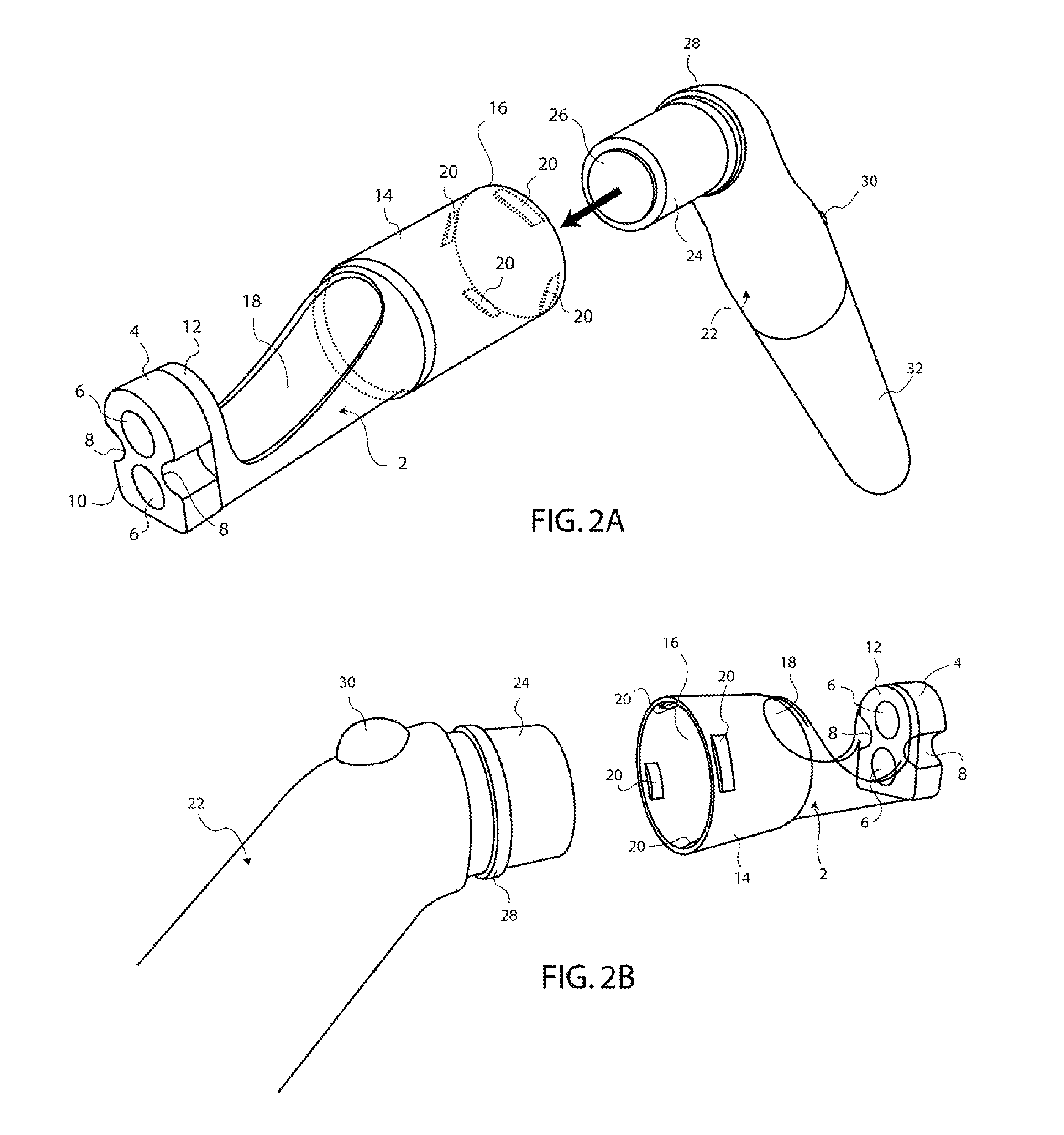
[0078]A preferred embodiment of the cure through veneer applicator with LED light is illustrated in FIG. 1A (anterior three quarter view), FIG. 1B (lateral orthographic view), FIG. 2A Anterior undocked dimensional view), FIG. 2B (Posterior undocked dimensional view), FIG. 3A (anterior dimensional view of the applicator portion) and FIG. 3B (posterior dimensional view of the applicator portion). The cure through veneer applicator has two primary aspects. The first is a disposable photo transmissible attachment or cure through compressible insert 2. This insert 2 is designed to interlock and attach with a slender handheld photo curing LED device 22. The LED device 22 is based upon currently available technologies. The attached combination of cure through insert 2 and LED device 22 desirably correlates both portions. This combined correlation permits the transmission of curing LED light from the LED device 22 through the cure through compressible inse...


PUM


Abstract

A veneer applicator to compressively place and photo cure a restorative covering to a tooth to include a photo transmissible insert (2) having a compressible applicator (4) with at least one traversing aperture (6) and a photo transmissible insert shaft (14) to dock with an LED device (22). Docking the insert shaft (14) with the LED device (22) permits a photo curing spectrum to traverse the shaft (14) and compressible applicator (4) at least one aperture (6). This allows for direct surface bonding during veneer application.

Description

CROSS REFERENCE TO RELATED APPLICATIONS[0001]This application claims the benefit of Provisional Patent Application Ser. No. 61 / 007,373 filed 2007 Dec. 12, by the present inventorFEDERALLY SPONSORED RESEARCH[0002]Not ApplicableSEQUENCE LISTING OR PROGRAM[0003]Not ApplicableFIELD OF INVENTION[0004]This invention applies to the field of Dentistry specifically to allow for the simultaneous controlled placement and curing of an indirect dental veneer to a tooth surface with a singular instrument.BACKGROUNDPrior Art[0005]To enhance the esthetic appearance of a tooth, or restore it to its anatomical original form, it may be necessary to place a tooth-like cover or veneer onto its facial or outer surface. After the tooth is prepared, an impression of it is sent to a laboratory which fabricates the veneer and returns it to the clinician for insertion into the patient's mouth. The intended tooth surface is then prepared to receive the veneer by being etched and primed. Having done this, a bon...

Claims


Application Information

Patent Timeline
Patent Type & Authority Patents(United States)
IPC IPC(8): A61C3/00A61C3/04A61C1/14A61C5/04
CPCA61C3/00A61C5/002A61C19/004A61C5/20
Inventor VISCOMI, BRIAN D.
Owner VISCOMI BRIAN D
Learn More