Hanging display system

a display system and display technology, applied in the direction of curtains, instruments, curtains, etc., can solve the problems of battery-powered signs, too sporadic outlet layout, and both approaches have drawbacks

Inactive Publication Date: 2011-08-30
PROCESS DISPLAY LLC
View PDF28 Cites 57 Cited by
  • Summary
  • Abstract
  • Description
  • Claims
  • Application Information

AI Technical Summary

Benefits of technology

[0010]An object of the present invention is to provide an improved method and system for hanging displays.

Problems solved by technology

Both of these approaches have drawbacks.
In the retail environment, the location of product and therefore signage is constantly changing, but the electrical outlets are static, and the layout of outlets is too sporadic and normally not designed with product layout in mind.
Batteries powered signs have limitations as well.
Batteries need to be replaced, and can only provide a minimal amount of power.
Further, the use of batteries adds weight to the installation which can be problematic given the ceiling grids are not normally designed to support a great deal of additional weight.
This is inconvenient, and can lead to simply letting the batteries run all the time, which is wasteful.
Finally, batteries are a relatively expensive source of electricity.

Method used


Image

  • Hanging display system
  • Hanging display system
  • Hanging display system

Examples


Embodiment Construction

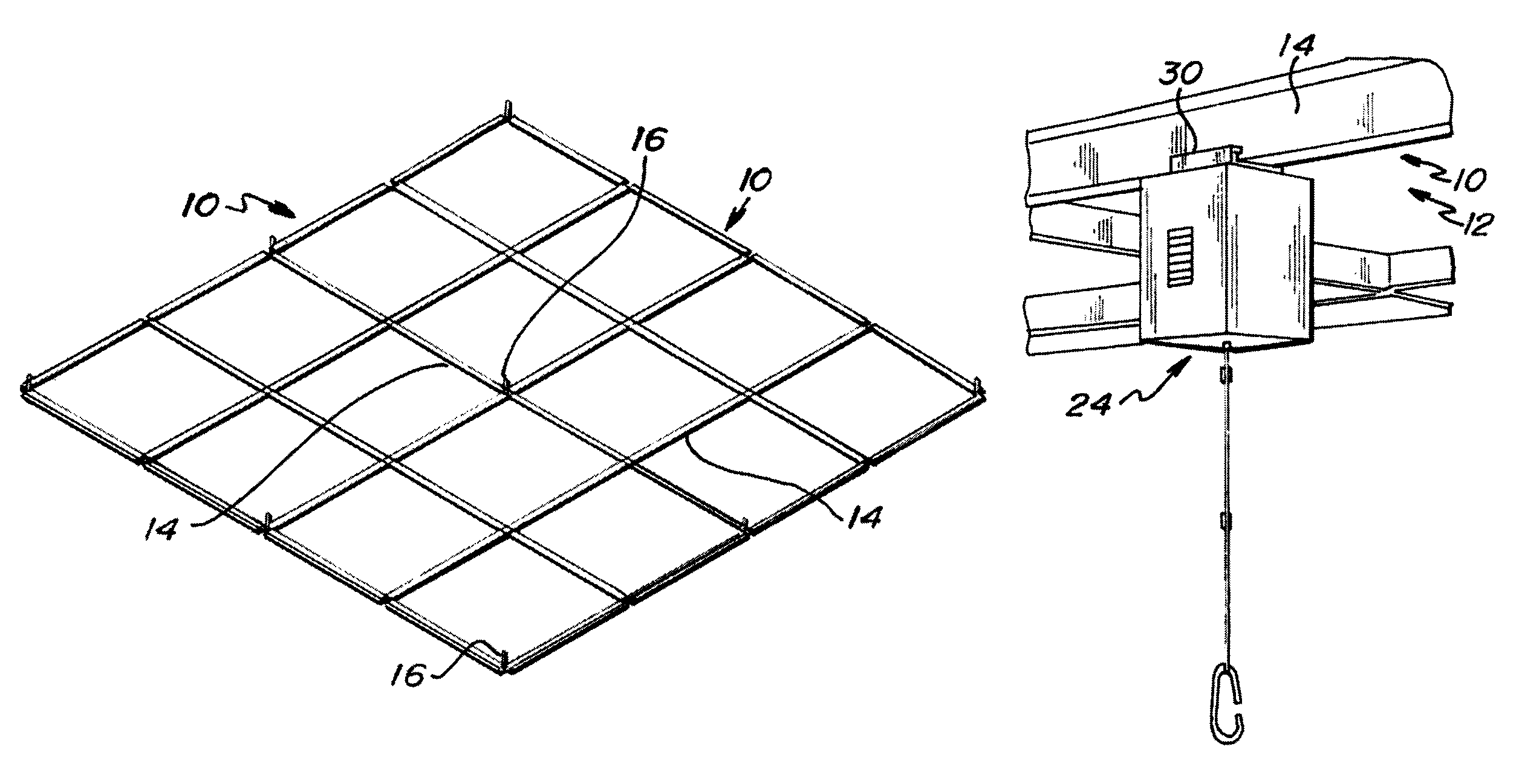
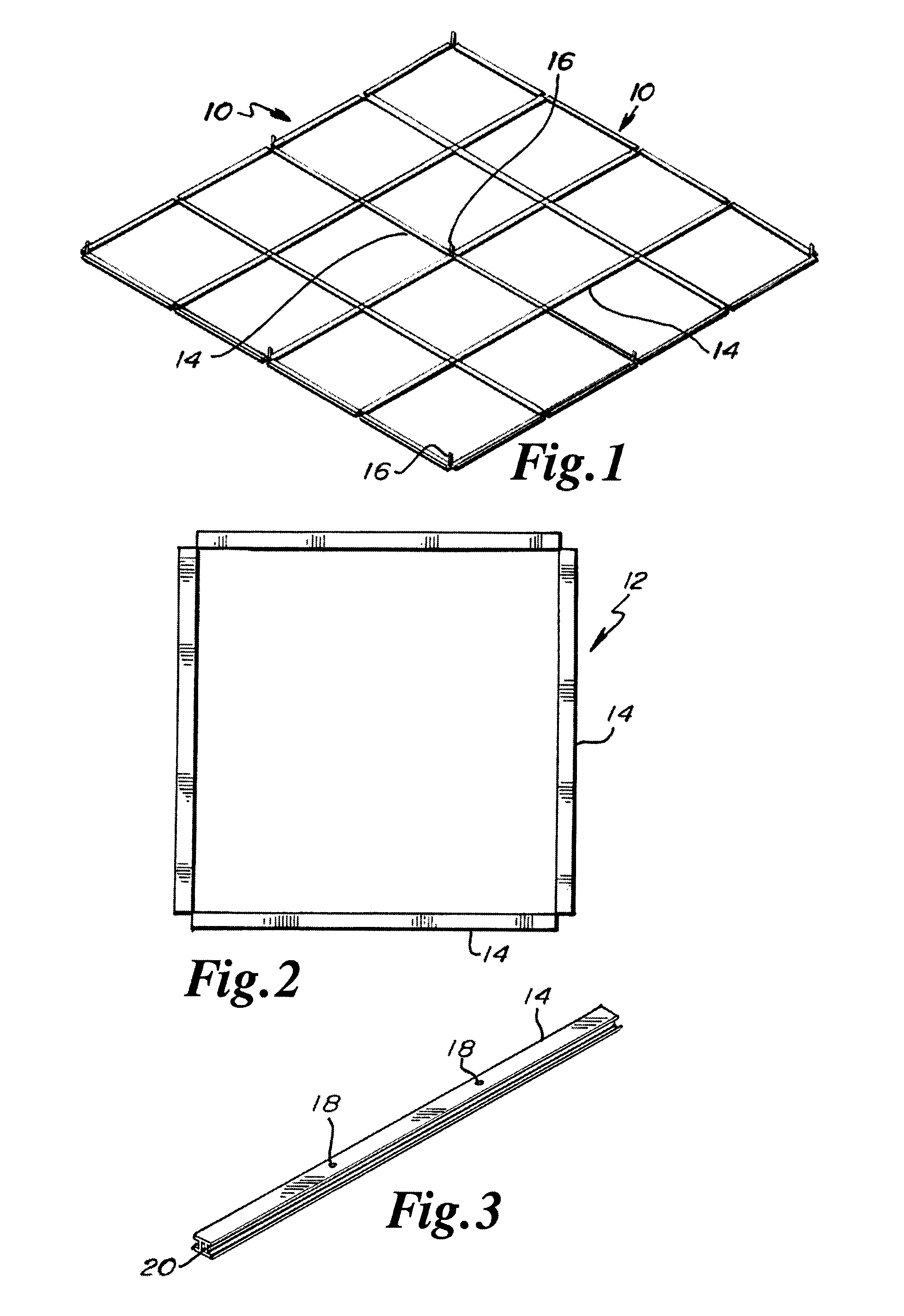
[0034]In the Figures, is shown a hanging display system 10. FIG. 1, shows a ceiling grid 12 of the system 10, which is adapted to attach to an existing drop-down ceiling. The ceiling grid 12 includes a plurality of grid members 14 which make up the structural components of the grid 12. The grid 12 is sized to fit the pattern and size of an existing ceiling tile system. Those of ordinary skill in the art will understand that the size of the grid 12 can and will vary. The grid 12 also includes a plurality of grid mounts 16 which connect to the existing ceiling grid. The grid mounts 16 can connect using any conventional connection system, such as, screws, bolts, snap on connectors, or they can be adapted to secure to the existing runners and cross-tees of the existing drop down ceiling. Sufficient grid mounts 16 can be included to accommodate the size and weight of the ceiling grid 12. In place, the grid 12 will mount nearly flush with the existing drop-down ceiling.

[0035]FIG. 2 is a v...


PUM


Abstract

A hanging display system is provided comprising an electrified grid system adapted for operative communication with display animation modules.

Description

CROSS-REFERENCE TO RELATED APPLICATION[0001]The present application claims priority to, and incorporates by reference thereto, U.S. Provisional Patent Application No. 61 / 188,810 filed on Aug. 13, 2008 entitled Hanging Display System.FIELD OF THE INVENTION[0002]This invention relates to a system for hanging displays. In particular, the invention relates to an electrified hanging display system adapted for use with a wide variety of advertising and promotional signage typically used in retail environments.BACKGROUND OF THE INVENTION[0003]Suspended ceiling tile systems are well-known in the art. These systems are found in a wide variety of commercial buildings, and even in residential homes. Sometimes called drop-down ceilings, the systems typically are comprised of a support grid secured to the walls and / or suspended from the ceiling / roof, wherein tiles fit between the grid units.[0004]Characteristic systems will include a perimeter molding, or edge piece, that can be affixed to the w...

Claims


Application Information

Patent Timeline
Patent Type & Authority Patents(United States)
IPC IPC(8): E04B9/00G09F7/18G09F7/22
CPCG09F7/18G09F2007/186
Inventor ANDERSON, RICHARD
Owner PROCESS DISPLAY LLC
Why Eureka
Try Eureka