Method for forming staple pockets of a surgical stapler

a technology of surgical stapler and staple pocket, which is applied in the direction of surgical staples, manufacturing tools, surgery, etc., can solve the problems of insufficient precision of staple pocket formation, insufficient tolerance, and damage to surgical stapler

Active Publication Date: 2011-08-30
TYCO HEALTHCARE GRP LP
View PDF20 Cites 605 Cited by
  • Summary
  • Abstract
  • Description
  • Claims
  • Application Information

AI Technical Summary

Benefits of technology

[0005]Example embodiments of the present invention relate to a system and method for forming a staple pocket, e.g., on the anvil portion of a surgical stapler device. In an example embodiment, a laser-machining system includes a laser-emitting device that is configured to emit a laser beam or beams for forming staple pockets on the anvil of a surgical stapler. The staple pockets of an anvil may be formed successively or simultaneously. The anvil of the surgical stapler is mounted in a mounting mechanism so as to control its movement, and the laser-emitting device is controlled by a control module, which may control any aspect of the laser-machining operation, e.g., the intensity of the laser beam, the movement of the laser-emitting device relative to the anvil, etc. The control module may be a processor that includes software that provides instructions for the operation of the control module, and may be programmable by a user for inputting parameters, e.g., shape, arrangement, etc., corresponding to the staple pockets.

Problems solved by technology

One problem that is encountered by conventional methods of forming surgical staple pockets is that the staple pockets are not sufficiently precisely formed, e.g., they do not satisfactorily meet the small tolerances in alignment, depth and smoothness that are desired in surgical staplers.
Furthermore, the conventional methods of forming surgical staple pockets in the anvil of the surgical stapler may cause structure fractures of the anvil, thereby damaging the surgical stapler and adversely effecting the operation of the surgical stapler.
Still further, the conventional methods of forming surgical staple pockets in the anvil of the surgical stapler may cause the formation of uneven pocket surfaces, causing the surgical stapler to operate ineffectively.
Still further, the conventional methods of forming surgical staple pockets in the anvil of the surgical stapler may not provide for the formation of different or complex staple pocket shapes.
Still further, the conventional methods of forming surgical staple pockets in the anvil of the surgical stapler do not provide adequate consistency of the staple pockets over time—for instance, a coining tool when used over a period of time to form numerous staple pockets gradually experiences wear which, over time, may result in the formation of different shaped staple pockets over that period of time.
Still further, the conventional methods of forming surgical staple pockets in the anvil of the surgical stapler may not permit the shape of a staple pocket to be easily or quickly modified, because, if a different staple pocket shape is desired, a new coining tool must be designed, fabricated and installed in the coining device.

Method used


Image

  • Method for forming staple pockets of a surgical stapler
  • Method for forming staple pockets of a surgical stapler
  • Method for forming staple pockets of a surgical stapler

Examples


Embodiment Construction

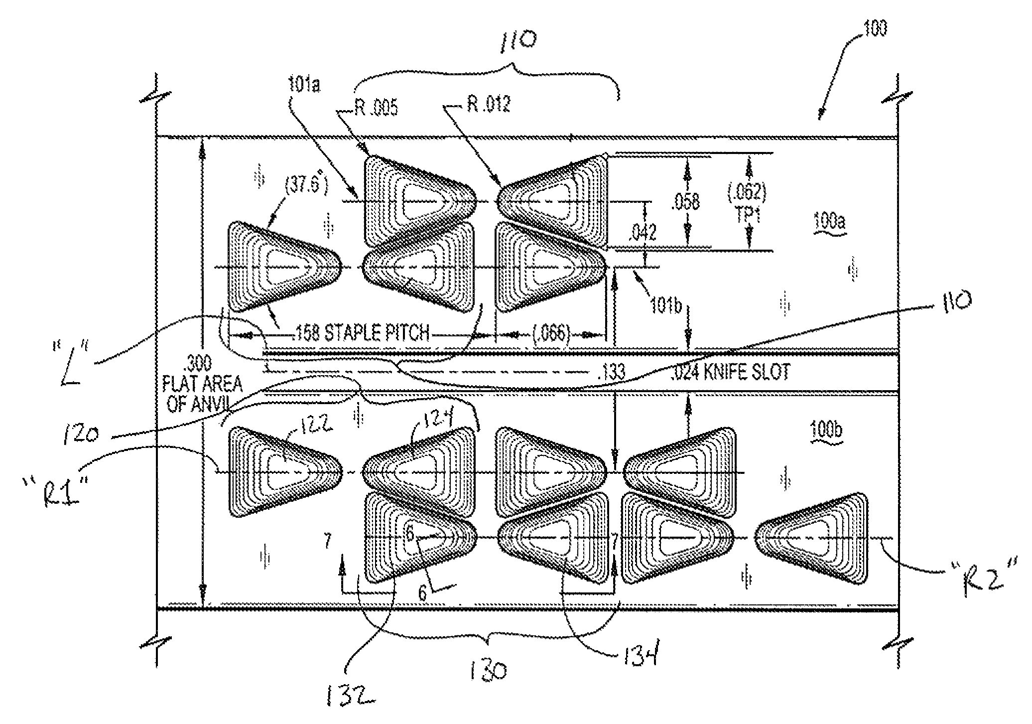
[0015]Systems and methods for forming a staple pocket are described herein. In example embodiments of the present invention, a system and method are for forming a staple pocket on the anvil of a surgical stapler. It should be understood that, although example embodiments of the present invention are described herein by way of example in connection with the formation of a staple pocket on the anvil of a surgical stapler, example embodiments of the present invention may also be employed to form staple pockets on other portions of a surgical device or on other types of surgical devices.

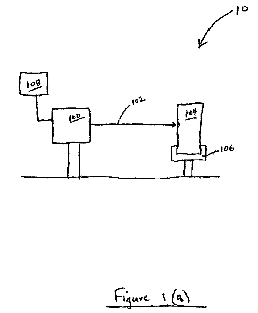
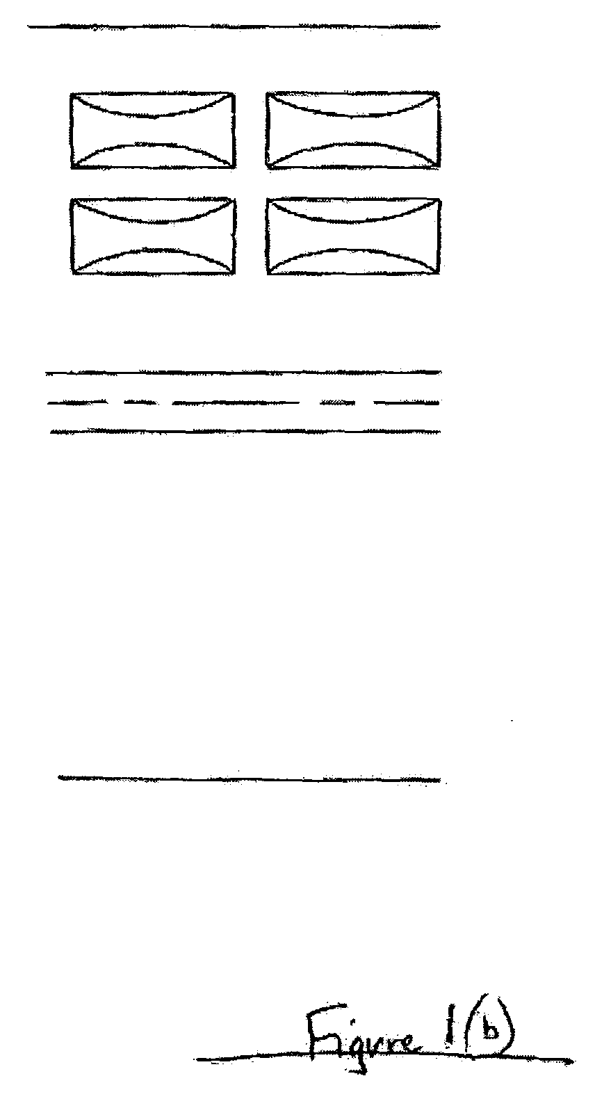
[0016]According to an example embodiment of the present invention, the staple pockets are formed by a laser. FIG. 1(a) is a diagram that illustrates schematically some of the components of a laser-machining system 10. For instance, FIG. 1(a) illustrates a laser-emitting device 100 that is configured to emit a laser beam 102 (or more than one laser beam 102). The staple pockets of an anvil may be formed s...


PUM

PropertyMeasurementUnit
slope angleaaaaaaaaaa
shapeaaaaaaaaaa

Abstract

A system and method for forming a staple pocket, e.g., on the anvil portion of a surgical stapler device. A laser-machining system may include a laser-emitting device that is configured to emit a laser beam or beams for forming staple pockets on the anvil of a surgical stapler. The staple pockets of an anvil may be formed successively or simultaneously. The anvil of the surgical stapler is mounted in a mounting mechanism so as to control its movement, and the laser-emitting device is controlled by a control module, which may control any aspect of the laser-machining operation, e.g., the intensity of the laser beam, the movement of the laser-emitting device relative to the anvil, etc. The control module may be a processor that includes software that provides instructions for the operation of the control module, and may be programmable by a user for inputting parameters, e.g., shape, arrangement, etc., corresponding to the staple pockets.

Description

CROSS-REFERENCE TO RELATED APPLICATIONS[0001]This application claims the benefit of U.S. Provisional Patent Application Ser. No. 60 / 703,493 entitled “System and Method for Forming Staple Pockets of a Surgical Stapler”, filed Jul. 27, 2005, which is expressly incorporated herein in its entirety by reference thereto.FIELD OF THE INVENTION[0002]The present invention relates to a system and method for forming a staple pocket. More specifically, the present invention relates to a system and method for forming a staple pocket on an anvil of a surgical stapler.BACKGROUND INFORMATION[0003]Surgical staplers typically employ an anvil having staple pockets defined therein. Staples are pushed out of a staple cartridge through a section of tissue and against the staple pockets, the staple pockets being shaped so as to receive and progressively bend the legs of the staple into a closed position. More specifically, upon the firing of a staple firing mechanism of a surgical stapler, the staples are...

Claims


Application Information

Patent Timeline
Patent Type & Authority Patents(United States)
IPC IPC(8): B23K26/38
CPCA61B17/0686B23K26/365A61B2017/00526A61B2017/07264A61B17/072B23K26/361
Inventor WHITMAN, MICHAEL P.BURBANK, JOHN E.MALINOUSKAS, DONALD
Owner TYCO HEALTHCARE GRP LP
Why Eureka
Try Eureka