Painting device

a technology of painting device and paint brush, which is applied in the direction of cleaning equipment, brushes, carpet cleaners, etc., can solve the problem of not having a more universal painting devi

Inactive Publication Date: 2011-09-27
MORRIS LAMONT C
View PDF4 Cites 12 Cited by
  • Summary
  • Abstract
  • Description
  • Claims
  • Application Information

AI Technical Summary

Benefits of technology

[0007]In accordance with other aspects of the present invention the flanges each have a hole therein for receiving end posts of the paint roller; including, on the one side of the support end, a tapered wall surface that is contiguous with the handle and to which are attached the spaced apart flanges at end thereof; wherein the tapered wall surface has a top end that extends between the flanges and a smaller bottom end that merges with the handle; wherein the paint pad means comprises a base and a paint absorption layer attached to the base; wherein the base and paint absorption layer both include a right angle bend forming respective back and side pad sections; wherein the back pad section is for support against a back of the wall member and the side pad section is for support against an end wall surface; wherein the paint pad means comprises a pair of paint pads, each including a right angle bend forming respective back and side pad sections; wherein each paint pad has end engagement ribs, one rib on a free end of the back pad section and another rib on a free end of the side pad section; wherein the wall member has a central aperture for receiving respective one ribs of the pair of paint pads at opposed side edges of the aperture; wherein the opposed end wall surfaces of the support end of the frame each have engagement ledges for receiving respective another ribs of the side pad sections; wherein the paint pad means comprises a pair of paint pads, each including a right angle bend forming respective back and side pad sections, and the wall member has a central aperture for receiving respective ends of the pair of paint pads at opposed side edges of the aperture and wherein the opposed end wall surfaces of the support end of the frame each have engagement ledges for receiving respective free ends of the side pad sections.

Problems solved by technology

However, a more universal painting device does not exist at the present time that can readily incorporate both the roller and pad functions.

Method used


Image

  • Painting device
  • Painting device
  • Painting device

Examples


Embodiment Construction

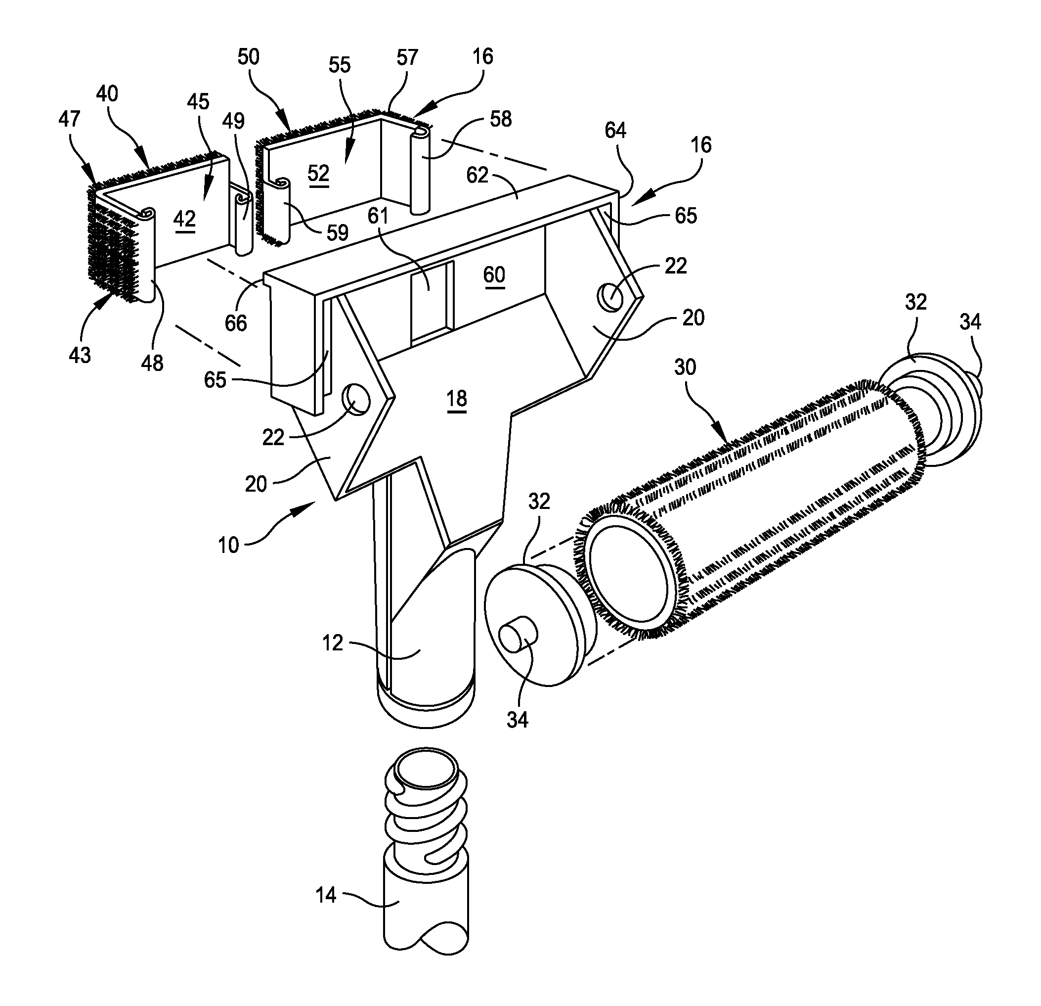
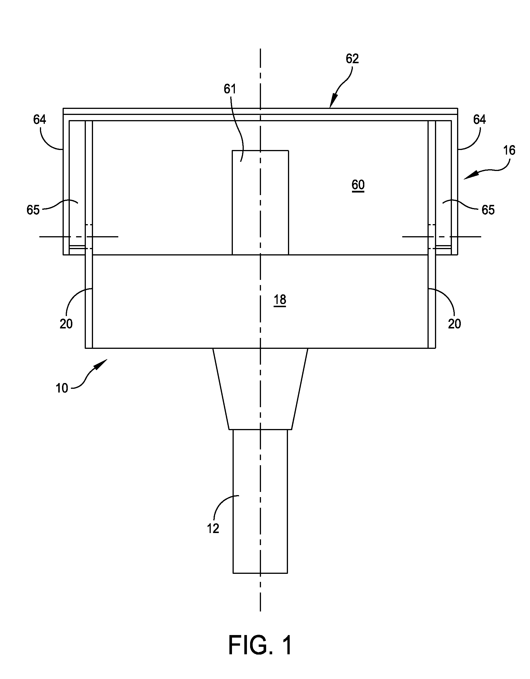
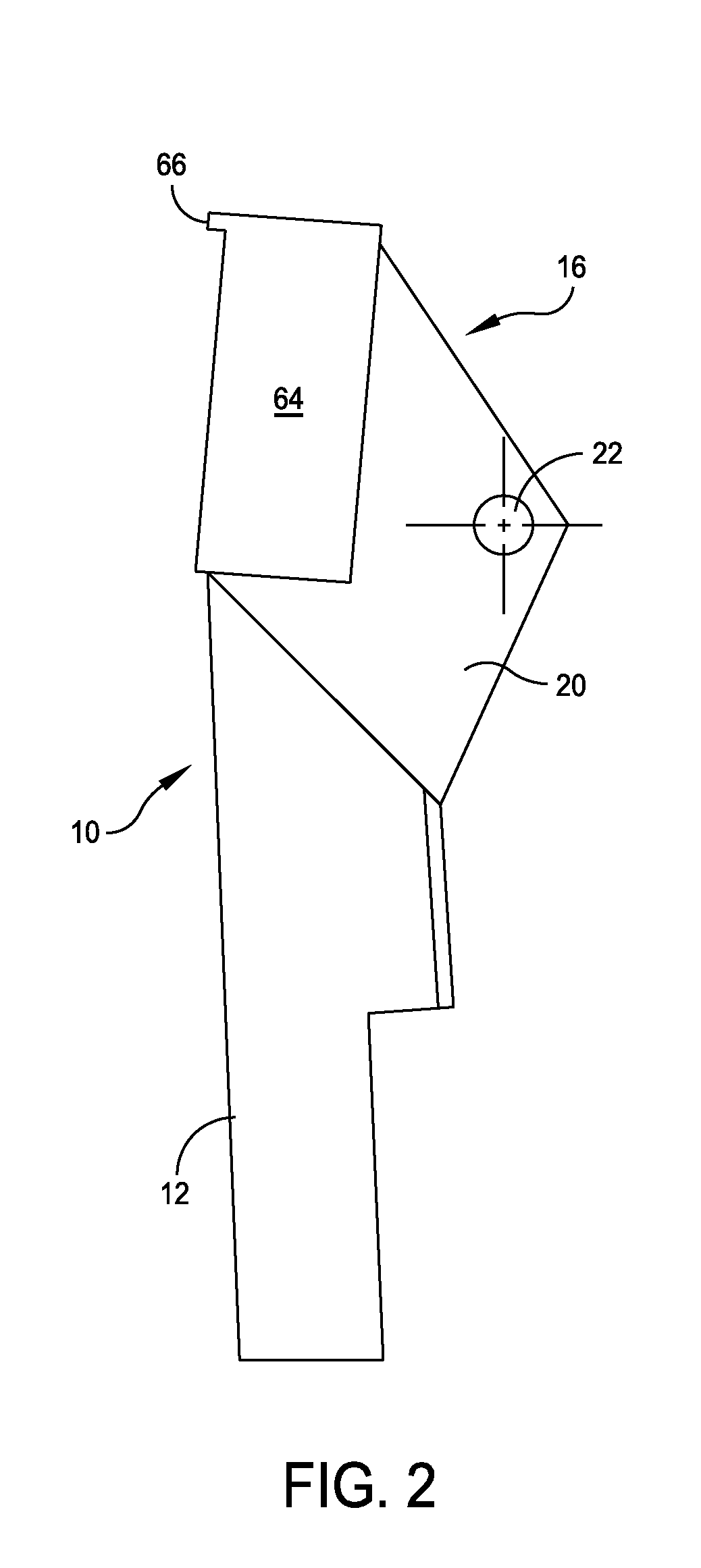
[0021]Reference is now made to the drawings and in particular to FIGS. 1-4. FIGS. 1-4 illustrate the basic frame construction. This is preferably constructed of a hard plastic material. FIGS. 5-8 illustrate various views also of the frame but with the roller and pad structures supported by the frame. FIG. 9 is a partially cut away front view illustrating further details and FIG. 10 is an exploded perspective view. The roller itself may be of conventional design as is presently used with a standard handle that is used in the industry. The pad structures are particularly designed for use in accordance with the present invention.

[0022]The painting device is comprised of a frame 10 that includes a handle 12. The handle 12 may be square, rectangular or circular in cross-section. In FIG. 10 the handle 12 is illustrated as of cylindrical shape and has an internally threaded port for receiving a threaded end of a pole 14 that can be used as an extension for the painting device. The frame 10...


PUM


Abstract

A painting device for applying a paint product and that includes a frame with a handle end and a support end and that has one and another sides. The one side of the support end of the frame includes spaced apart flanges that retain therebetween a paint roller and the another side of the support end of the frame includes a wall member and opposed end wall surfaces that together retain a paint pad device.

Description

TECHNICAL FIELD[0001]The present invention relates in general to a painting device and pertains, more particularly, to an improved painting device that incorporates in an integral manner both a paint roller and paint pad.BACKGROUND OF THE INVENTION[0002]At the present time there exists a number of different implements for assisting in painting, particularly in the interior of housings or buildings. These existing devices include, for example, a standard roller arrangement or a separate pad structure that is sometimes used for edging. However, a more universal painting device does not exist at the present time that can readily incorporate both the roller and pad functions.[0003]Accordingly, it is an object of the present invention to provide an improved painting device and in particular one that integrally arranges for the use of both a roller and a pad structure.[0004]Another object of the present invention is to provide an improved painting device that is relatively simple in const...

Claims


Application Information

Patent Timeline
Patent Type & Authority Patents(United States)
IPC IPC(8): B05C1/06B05C1/08B05C11/00B05C17/02A46B17/00A47L13/00
CPCA46B7/10B05C17/0217B05C17/0235A46B5/0008A46B2200/202
Inventor MORRIS, LAMONT C.
Owner MORRIS LAMONT C
Why Eureka
Try Eureka