Antenna switching system and method

a switching system and antenna technology, applied in the field of rfid readers, can solve the problems of inconvenient rfid techniques for certain applications, many man-hours of labor consumed, and the inability to identify and track assets

Inactive Publication Date: 2011-10-11
GENERAL ELECTRIC CO
View PDF4 Cites 2 Cited by
  • Summary
  • Abstract
  • Description
  • Claims
  • Application Information

AI Technical Summary

Problems solved by technology

Identifying and tracking assets is a considerable expense for any business that handles significant volumes of inventory.
Thus many man-hours of labor may be consumed just in asset tracking alone.
However, current RFID techniques may not be suitable for certain applications.
For example, international RF spectrum regulations often vary greatly, meaning that certain RFID tags may not be usable in all of the countries to which assets might be delivered.
Additionally, certain RFID tags may not operate reliably when used with assets that include a number of small metal items.

Method used


Image

  • Antenna switching system and method
  • Antenna switching system and method
  • Antenna switching system and method

Examples


Embodiment Construction

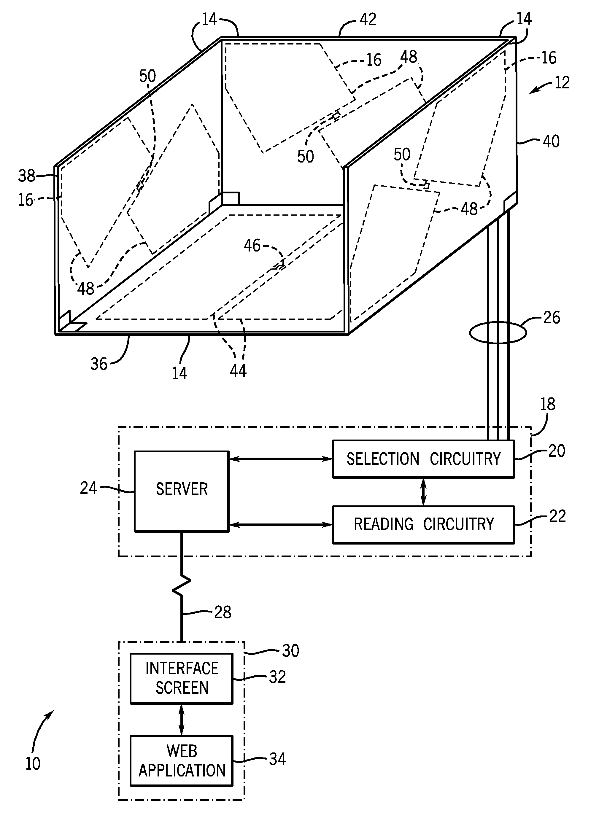
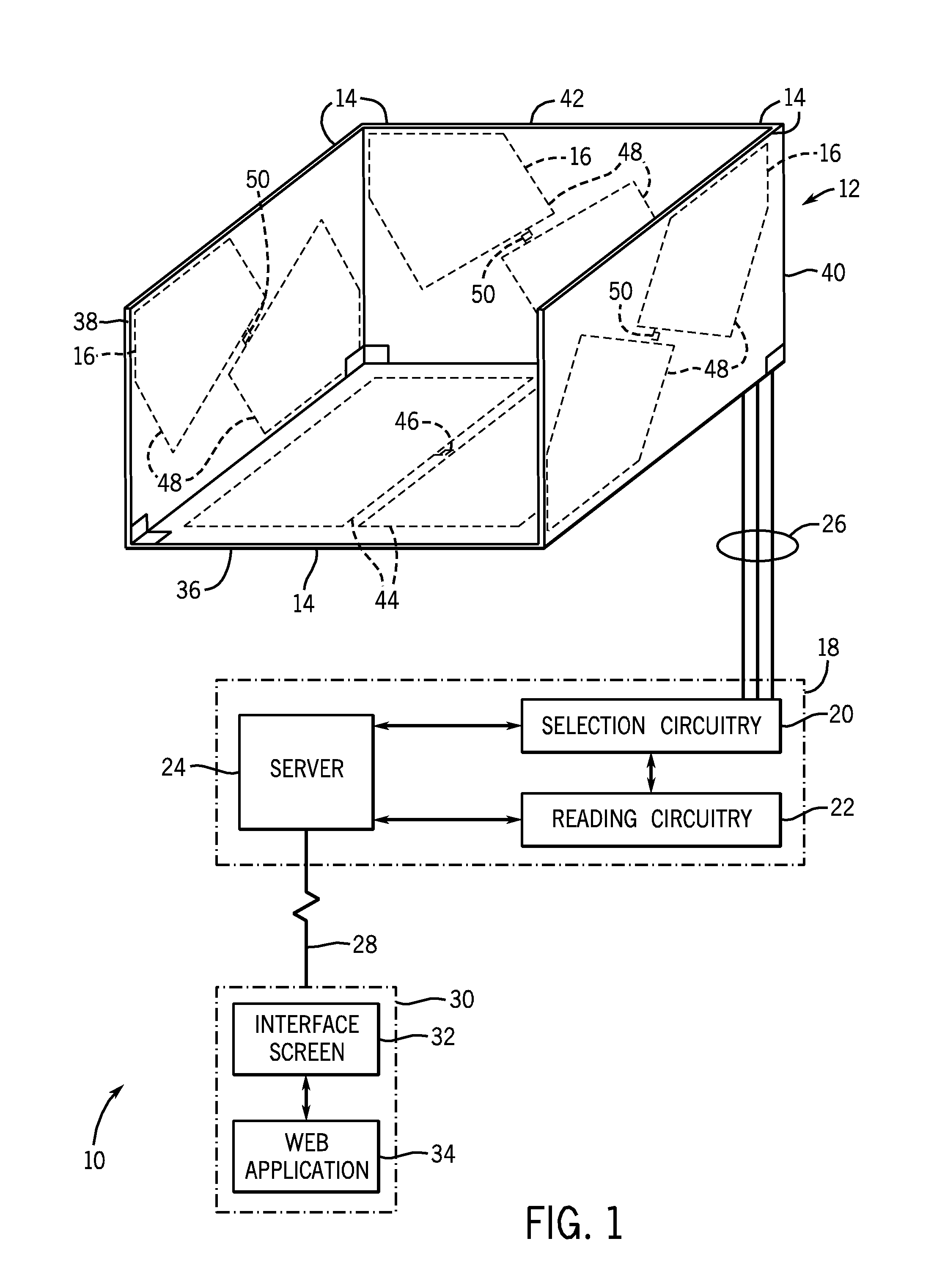
[0016]Embodiments of the present invention include a tag reading system 10 configured to operate in the LF frequency band. More specifically, embodiments of a tag reading system operate at or near 125 KHz. Operating a tag reading system in LF frequency band may be advantageous because certain segments of the LF band, such as 125 KHz, are available globally for RFID technology. Additionally, RFID tags in the vicinity of metal or liquids or other conductive materials tend to operate more reliably in the LF frequency band. Embodiments of the present invention also utilize several orthogonally oriented antennas that are activated sequentially. In this way, the effective range of the reader is beneficially extended over a volume, and the reader is able to read tags oriented in any direction.

[0017]FIG. 1 depicts a tag reading system 10 configured to generate asset tracking information in accordance with an embodiment of the present invention. The tag reading system 10 includes an antenna ...


PUM


Abstract

An improved RFID tag reader is provided. More specifically, an RFID tag reader is provided that includes a plurality of antenna panels arranged to form a sensing volume in which RFID tags are read. Additionally, the RFID tag reader includes a novel switching mechanism that activates the antenna panels in sequence while minimizing cross coupling between the antenna panels. Furthermore, a novel antenna geometry also reduces antenna cross coupling.

Description

BACKGROUND[0001]The invention relates generally to RFID readers. More specifically, the invention relates to an RFID reader with an antenna array and an antenna switching unit for selectively coupling or decoupling the antennas in the antenna array.[0002]Identifying and tracking assets is a considerable expense for any business that handles significant volumes of inventory. For example, inventory items that are brought to a storage facility must be identified, categorized and stored so that the items can be readily retrievable, while inventory items that are to be shipped from storage must again be identified to provide an accurate accounting of items remaining in storage. Additionally, entire inventories may need to be periodically recounted to ensure that accounted inventory levels remain accurate over time despite occasional human error. Thus many man-hours of labor may be consumed just in asset tracking alone. Similarly, in shipping applications, large quantities of different it...

Claims


Application Information

Patent Timeline
Patent Type & Authority Patents(United States)
IPC IPC(8): G08B13/14
CPCG06K7/10316G06K7/10336G06K7/10346
Inventor DEROSE, LYNN ANNSALVO, JOSEPH JAMESFORMAN, DOUGLAS ROYBENNETT, JANET SUEGOOD, BRANDON STEPHENINTRATOR, MORGAN FREDRICSCHIELI, NICOLAS AUGUSTE CONSTANT
Owner GENERAL ELECTRIC CO
Why Eureka
Try Eureka