Separating contaminants from gas ions in corona discharge ionizing bars

a technology of ionizing bars and contaminants, which is applied in the direction of magnetic separation, vapor flow control, variable capacitors, etc., can solve the problems of high voltage ionizing electrodes/emitters, electrical fields, and emi effects, and achieve the effects of preventing or decreasing fuzz balls, prolonging the maintenance-free time of such corona discharge electrodes, and improving ion delivery

Active Publication Date: 2011-10-18
ILLINOIS TOOL WORKS INC
View PDF49 Cites 23 Cited by
  • Summary
  • Abstract
  • Description
  • Claims
  • Application Information

AI Technical Summary

Benefits of technology

[0012]The present invention may satisfy the above-stated needs and overcome the above-stated and other deficiencies of the related art by providing ultra clean ionizing bars that provide one or more of the following benefits (1) provide static neutralization of charged neutralization targets / objects without exposing the targets / objects to substantial numbers of particulate contaminants inevitably produced by corona discharge electrodes in the ionizing bar; (2) provide static neutralization of charged targets / objects without exposing the charged neutralization targets / objects to substantial amounts of byproduct gases (such as ozone, nitrogen oxides, etc.) due to chemical reactions inevitably produced by corona discharge of the ionizing bar; (3) prevent or decrease fuzz ball and / or other debris formation / contamination on corona discharge electrodes in the ionizing bar to thereby prolong the maintenance-free time of such corona discharge electrodes; and (4) improve ion delivery to the charge neutralization targets / objects by combination of air (gas) assist techniques and / or multi-frequency corona ionization techniques.

Problems solved by technology

These charges generate undesirable electrical fields, which attract atmospheric aerosols to the surfaces, produce electrical stress in dielectrics, induce currents in semi-conductive and conductive materials, and initiate electrical discharges and EMI in the production environment.
Gas ionization of this type permits effective compensation or neutralization of undesirable charges and, consequently, diminishes contamination, electrical fields, and EMI effects associated with them.
However, one known drawback of such corona discharge apparatus is that the high voltage ionizing electrodes / emitters (in the form of sharp points or thin wires) generate undesirable contaminants along with the desired gas ions.
This approach, however, has its own drawback: it often requires the use of emitter material, such as tungsten, which is foreign to the technological process, such as semiconductor manufacturing.
The preferred silicon emitters for ionizers used to neutralize charge during the manufacture of semiconductor silicon wafers do not possess the desired etching and corrosive resistance.
Consequently, in the ambient ionizer vacuum flow alone does not solve the problem of emitter contamination.

Method used


Image

  • Separating contaminants from gas ions in corona discharge ionizing bars
  • Separating contaminants from gas ions in corona discharge ionizing bars
  • Separating contaminants from gas ions in corona discharge ionizing bars

Examples


Embodiment Construction

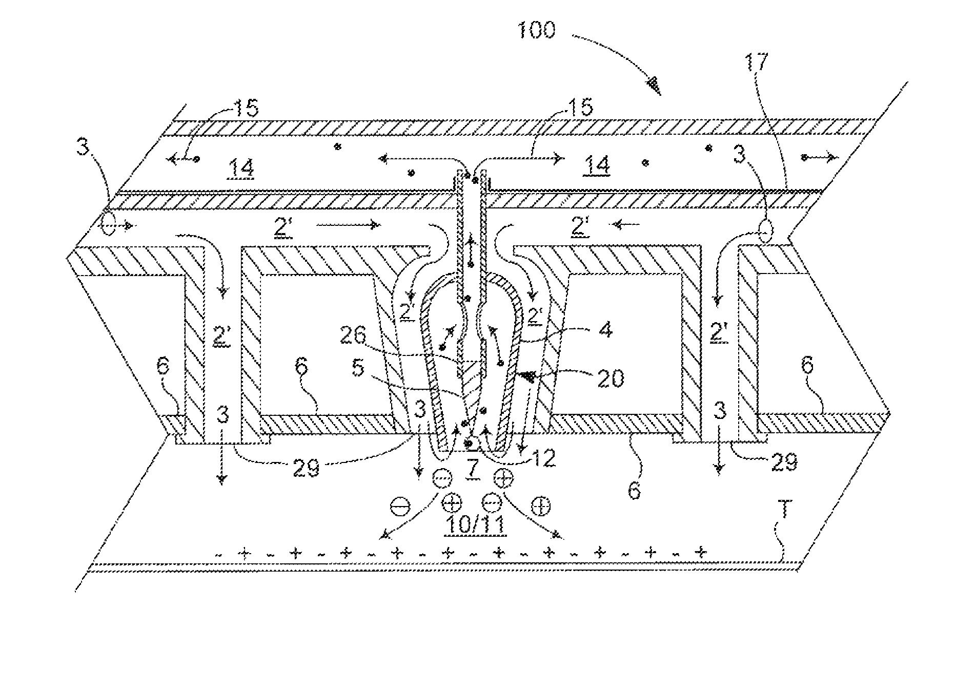
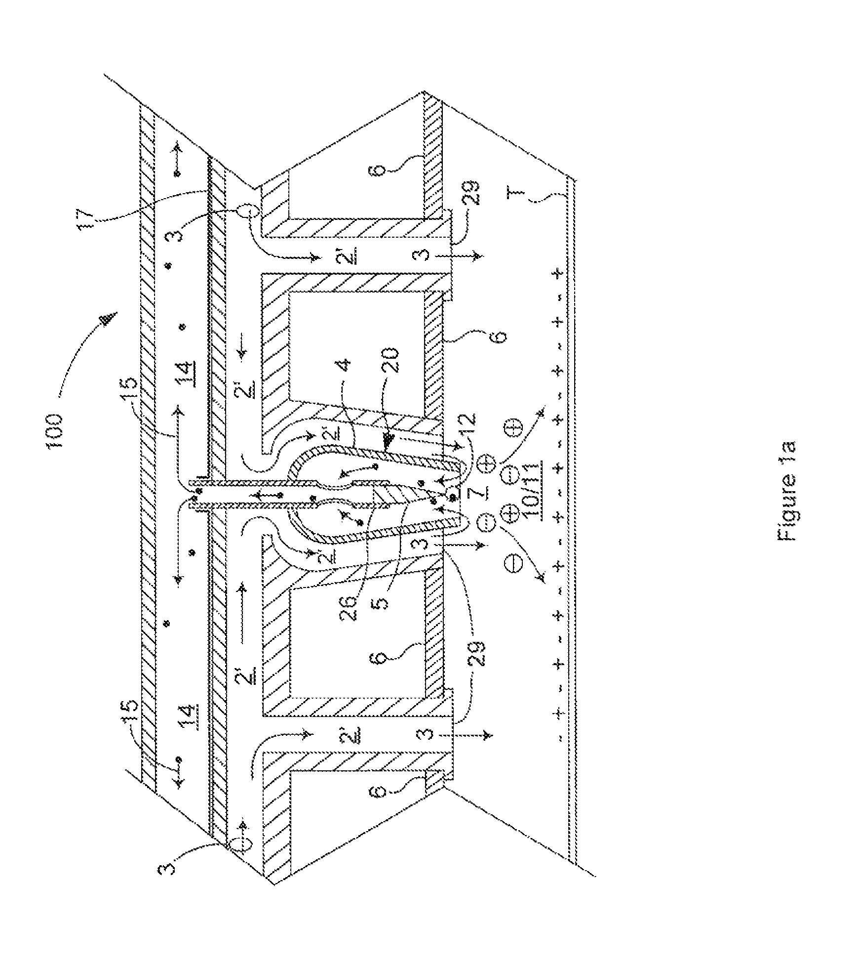
[0027]The inventive concept of a preferred ultra-clean AC corona ionizing bar 100 is illustrated in the fragmented cross-sectional view of FIG. 1a. As shown therein, a preferred linear ionizing bar 100 may comprise a plurality of linearly disposed shell assemblies 20 (each having an emitter 5 and a shell 4) which may be separated by a plurality of nozzles / ports 29 that are in gas communication with a non-ionized air / gas channel 2′ and that are directed toward a charged neutralization target / object T. Air / gas port(s) / nozzle(s) 29 may assist with the delivery of charge carriers 10 / 11 toward charged target / object T. Additionally, ionizing bar 100 may contain a low-pressure evacuation channel 14. Evacuation channel 14 may be connected to an in-tool / production vacuum line (not shown), to a built-in vacuum source (not shown), or to any of the many similar arrangements known in the art that may maintain a pressure that is lower than the gas pressure in the vicinity of the emitter shell ori...


PUM


Abstract

Clean corona ionization bars separate contaminant byproducts from corona generated ions by establishing a non-ionized gas stream having a pressure and directed toward an attractive non-ionizing electric field of a charge neutralization target, by establishing a plasma region of ions and contaminant byproducts in which the pressure is sufficiently lower than the pressure of the non-ionized gas stream to prevent byproducts from migrating into the non-ionized gas stream. The ionization bar(s) may be located sufficiently close to the charged neutralization target that a non-ionizing electric field of the target induces at least a substantial portion of the ions to migrate into the non-ionized gas stream and to the neutralization target as a clean ionized gas stream.

Description

CROSS REFERENCE TO RELATED CASES[0001]This application claims the benefit under 35 U.S.C. 119(e) of co-pending U.S. Application Ser. No. 61 / 337,701, filed Feb. 11, 2010 and entitled “Separating Contaminants From Gas Ions In Corona Discharge Ionizers”; and is a continuation-in-part of U.S. application Ser. No. 12 / 799,369, filed Apr. 23, 2010, which, in turn, claimed priority from U.S. Provisional Application Ser. No. 61 / 214,519 filed Apr. 24, 2009 and entitled “Separating Particles and Gas Ions in Corona Discharge Ionizers”; U.S. Provisional Application Ser. No. 61 / 276,792 filed Sep. 16, 2009 and entitled “Separating Particles and Gas Ions in Corona Discharge Ionizers”; U.S. Provisional Application Ser. No. 61 / 279,784, filed Oct. 26, 2009 and entitled “Covering Wide Areas With Ionized Gas Streams”; and U.S. Provisional Application Ser. No. 61 / 337,701, filed Feb. 11, 2010 and entitled “Separating Contaminants From Gas Ions In Corona Discharge Ionizers”, which applications are all here...

Claims


Application Information

Patent Timeline
Patent Type & Authority Patents(United States)
IPC IPC(8): B03C3/36
CPCB03C3/017B03C3/155B03C3/383B03C3/49B03C3/41B03C2201/24B03C2201/06
Inventor GEFTER, PETER
Owner ILLINOIS TOOL WORKS INC
Why Eureka
Try Eureka