Method and apparatus for aircraft anti-icing

a technology of aircraft wings and anti-icing, applied in mechanical equipment, machines/engines, transportation and packaging, etc., can solve the problems of aircraft wings, propeller air inlets, aircraft much more difficult to fly, and considerable weigh

Active Publication Date: 2011-11-22
GENERAL ELECTRIC CO
View PDF30 Cites 43 Cited by
  • Summary
  • Abstract
  • Description
  • Claims
  • Application Information

AI Technical Summary

Problems solved by technology

The formation of ice on aircraft wings, propellers, air inlets of engines, etc. has been a problem since the earliest days of heavier-than-air flight.
Any accumulated ice adds considerable weight, and changes the airfoil or inlet configuration making the aircraft much more difficult to fly and in some cases has caused loss of aircraft.
In the case of jet aircraft, large pieces of ice breaking loose from the leading edge of an engine inlet housing can damage rotating turbine blades or other internal engine components and cause engine failure.
While often useful, these systems are not fully effective due to the low quantity of hot gases introduced relative to the mass of air in the housing, the heating effect tending to be limited to the region near the hot gas introduction point, and the complexity of the hot gas duct system.
Both systems have limitations.
The impingement ring style anti-ice systems have a cumbersome tube and support structure that runs 360 degrees around the front inlet compartment.
While these systems generally have very high heat transfer ratios they are also very heavy.
Swirl nozzle systems are generally significantly lighter than impingement ring style systems and use less air to de-ice but suffer from lower heat transfer.

Method used


Image

  • Method and apparatus for aircraft anti-icing
  • Method and apparatus for aircraft anti-icing
  • Method and apparatus for aircraft anti-icing

Examples


Embodiment Construction

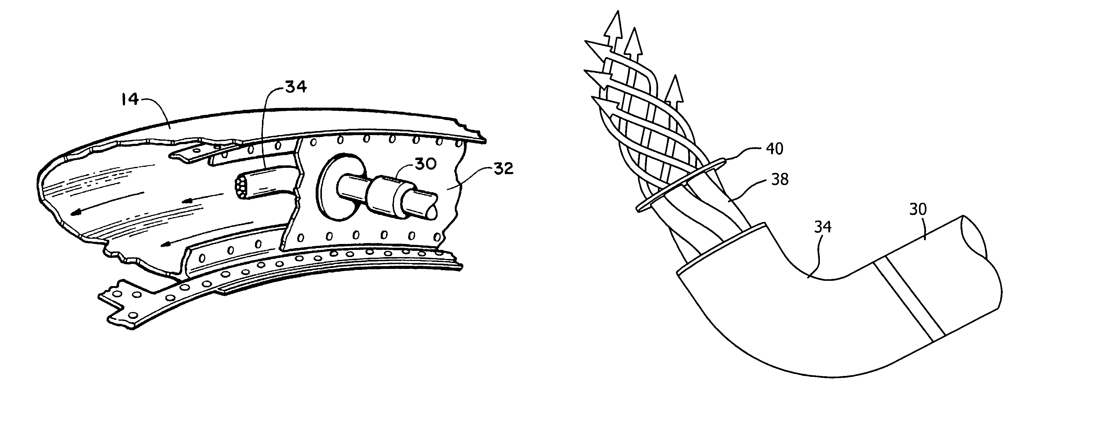
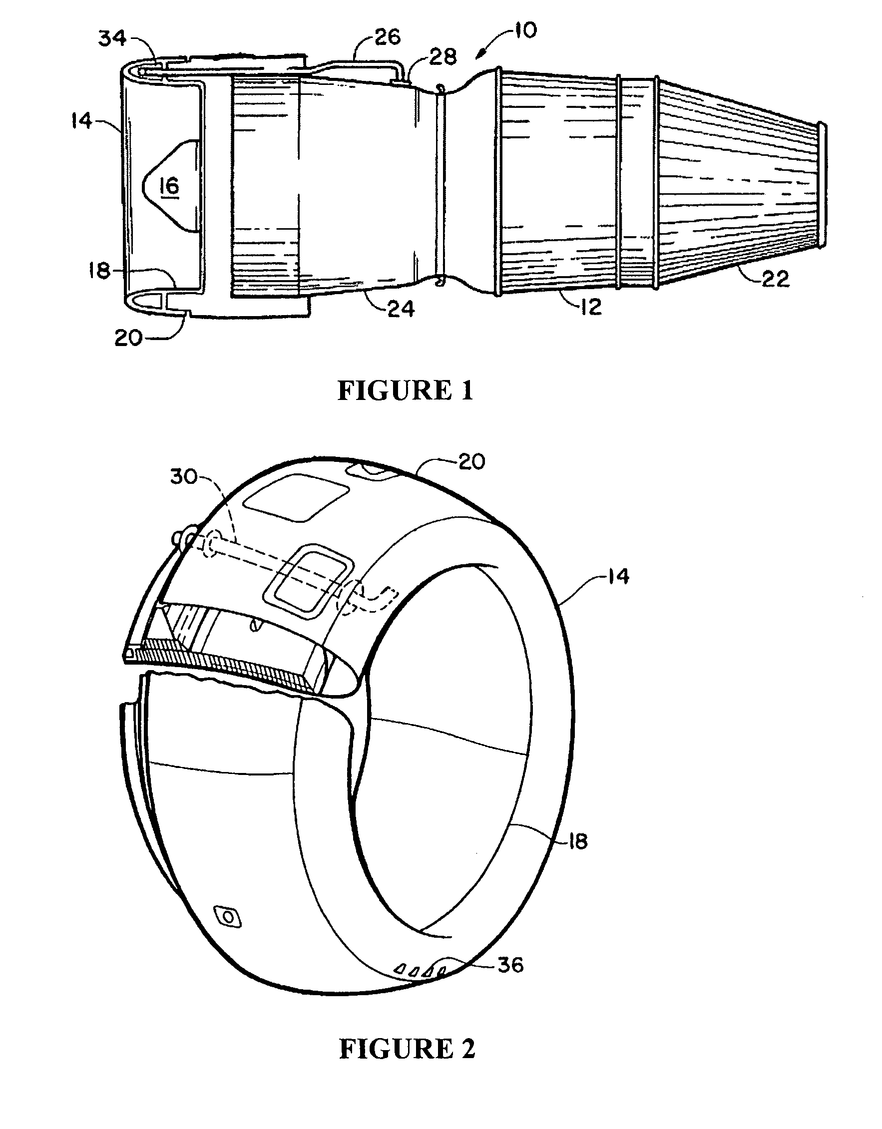
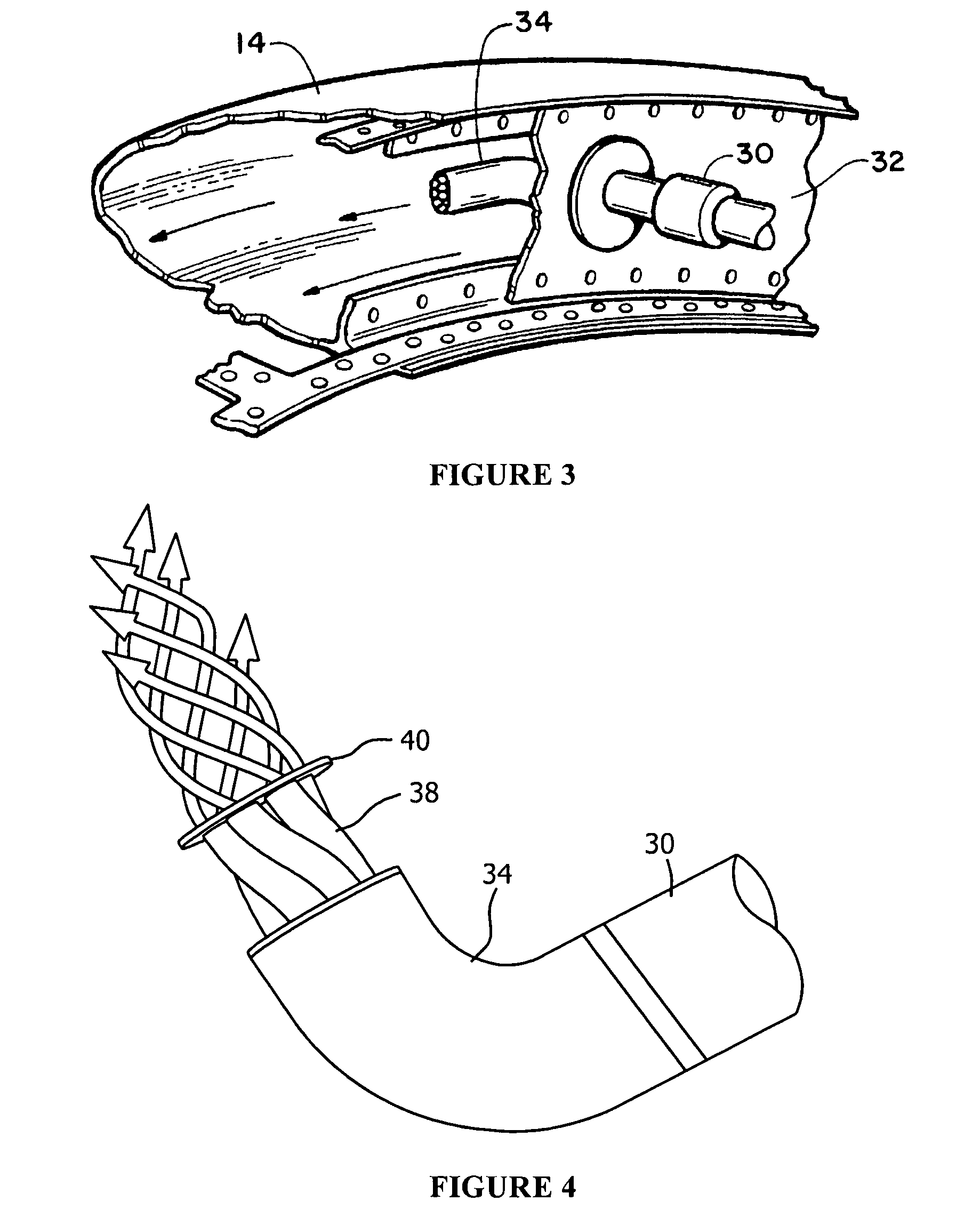
[0017]Referring now to the drawings in detail and in particular to FIG. 1, there is seen a schematic representation of a jet turbine engine 10 of the type suitable for aircraft propulsion. The turbine engine 10 is housed within a central housing 12. Air enters the engine 10 through an air inlet section 20, between the spinner 16 of the engine and the nose lip or annular single skin housing 14 which constitutes the forward most section of the air inlet 20 of the engine nacelle, some of which components have been omitted from the figure for simplicity. Engine thrust is produced by burning incoming air and fuel within the central housing 12 and passing the hot, high pressure propulsion gases through exhaust outlet 22 and out the rear of the engine.

[0018]In flight, ice tends to form on the nose lip 14 (in addition to other aircraft components omitted for simplicity). The ice changes the geometry of the inlet area 18 between the nose lip 14 and the spinner 16, adversely affecting the req...


PUM


Abstract

An aircraft anti-icing system includes a source of high temperature gas, a housing, at least one conduit to carry the high temperature gas from the source to the housing, the at least one conduit coupled to the housing and the source, at least one nozzle coupled to the at least one conduit, at least one nozzle configured to impart a rotational motion to the high temperature gas before exhausting the high temperature gas into the housing, and a port for exhausting air from the housing.

Description

BACKGROUND OF THE INVENTION[0001]The present invention relates to an improvement in anti-icing systems for aircraft jet engine propulsion systems.[0002]The formation of ice on aircraft wings, propellers, air inlets of engines, etc. has been a problem since the earliest days of heavier-than-air flight. Any accumulated ice adds considerable weight, and changes the airfoil or inlet configuration making the aircraft much more difficult to fly and in some cases has caused loss of aircraft. In the case of jet aircraft, large pieces of ice breaking loose from the leading edge of an engine inlet housing can damage rotating turbine blades or other internal engine components and cause engine failure.[0003]One of the most common anti-ice techniques has been the ducting of hot gases into a housing adjacent to the likely icing area. Current techniques to solve this problem generally fall into one of two types of systems: Impingement style ring systems or swirl nozzle systems. In each case, the h...

Claims


Application Information

Patent Timeline
Patent Type & Authority Patents(United States)
IPC IPC(8): B64D15/02
CPCB64D15/04B64D2033/0233B64D2033/0286
Inventor ROCKLIN, MARKKARVOUNTZI, GEORGIA C.HUMMEL, DANIEL S.
Owner GENERAL ELECTRIC CO
Why Eureka
Try Eureka