
Ice protection system and method

Active Publication Date: 2014-07-15
THE BOEING CO
View PDF13 Cites 18 Cited by
  • Summary
  • Abstract
  • Description
  • Claims
  • Application Information

AI Technical Summary

Benefits of technology

The present patent provides an ice protection system and method for preventing or reducing ice formation on an aerodynamic surface. The system uses induction coils to generate an electromagnetic field that creates eddy currents in the surface to heat it. The heating is efficient in terms of power consumption and does not substantially increase the weight of the surface. Overall, the system can effectively prevent or reduce ice formation on the surface without causing damage or added weight.

Problems solved by technology

Similarly, other aerodynamic surfaces, such as the blades of a wind turbine, may be subject to the formation of ice when exposed to icing conditions.
Ice formation upon a leading edge of an aircraft or other aerodynamic surface may have an adverse effect upon the performance of the aircraft, wind turbine or the like.
Such heating techniques may be insufficient, however, for aerodynamic surfaces that are not formed of thermally conductive materials.
As such, conventional heating methods may prove less effective than desired with respect to protecting an inlet lip surface having an acoustic panel from ice formation.
As will be apparent, ice protection systems that rely upon bleed air are not effective for electric aircraft or other systems that do not have bleed air available.
Moreover, the generally static air within the cells of the honeycomb core of an acoustic liner may also insulate the exterior surface from the bleed air, thereby reducing the heat transfer rate to the exterior surface and / or increasing the amount of bleed air required to protect the exterior surface from ice formation.
The wire mesh heating elements of a low-power electrical de-icing system may disadvantageously increase the weight of the aerodynamic surface and may consume a meaningful amount of power in order to support current flow through the entire wire mesh network.
As a result of the power consumption, the power supply of the low-power electrical de-icing system may need to be sized in such manner that it also disadvantageously increases the weight and the cost of the aerodynamic surface.
A transpiration flow anti-icing system requires engine bleed air and is therefore inapplicable with respect to an electric aircraft or other system in which bleed air is unavailable.
Also, since the upper temperature limit of the composite materials that are employed in acoustic liners is about 220° F. and since the bleed air temperatures are substantially higher, such as between about 800° F. and 1100° F., a transpiration flow anti-icing system may not be suitable for anti-icing an acoustically treated aerodynamic surface that employs composite materials.

Method used


Image

  • Ice protection system and method
  • Ice protection system and method
  • Ice protection system and method

Examples


Embodiment Construction

[0024]The present disclosure now will be described more fully hereinafter with reference to the accompanying drawings, in which some, but not all embodiments are shown. Indeed, the disclosure may be embodied in many different forms and should not be construed as limited to the embodiments set forth herein; rather, these embodiments are provided so that this disclosure will satisfy applicable legal requirements. Like numbers refer to like elements throughout.

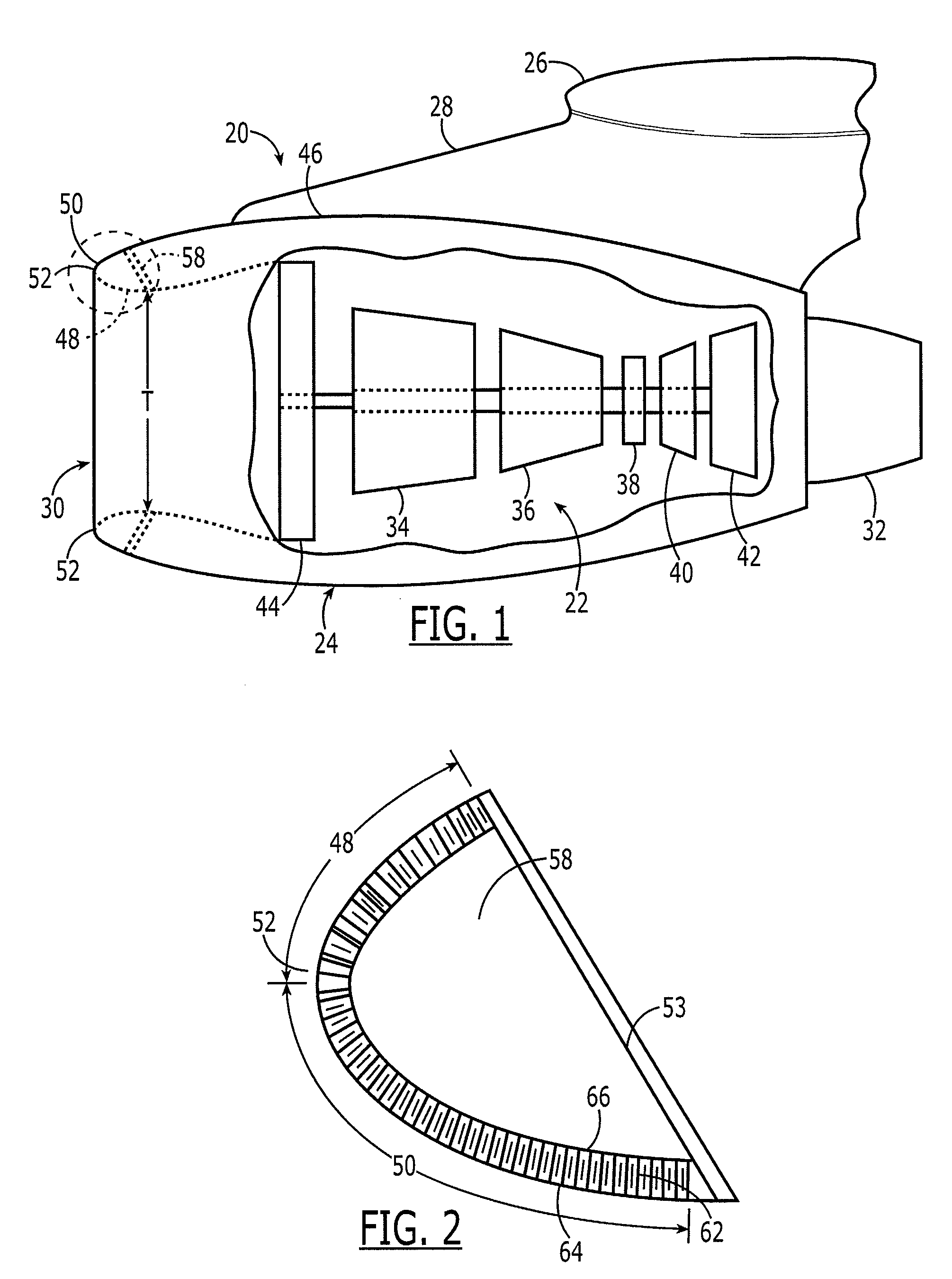
[0025]As described below, an ice protection system 10 and method are provided for preventing or reducing the formation of ice upon an aerodynamic surface. Although primarily described below in conjunction with the prevention or reduction of ice formation upon an engine nacelle inlet, the ice protection system and method may be employed in conjunction with a variety of other aerodynamic surfaces, such as the leading edge of an aircraft wing, the leading edge of a flap, the leading edge of a blade, such as a blade of a wind turbine...


PUM


Abstract

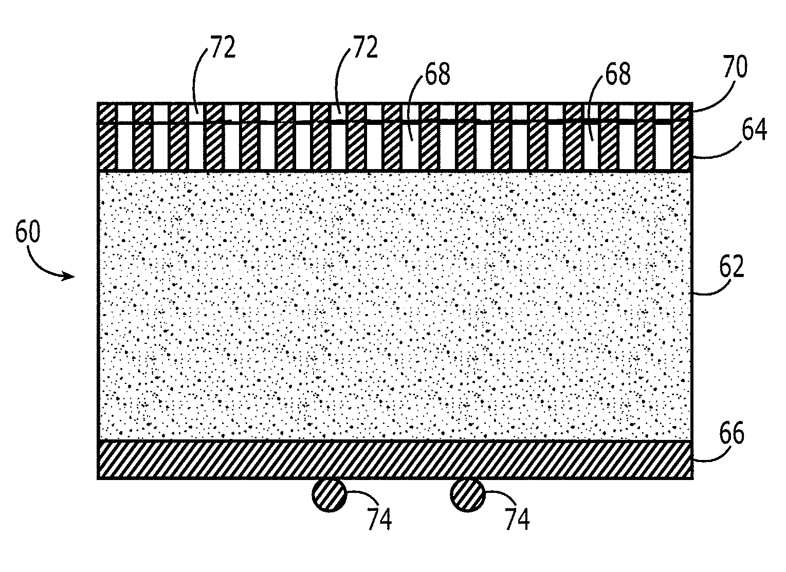
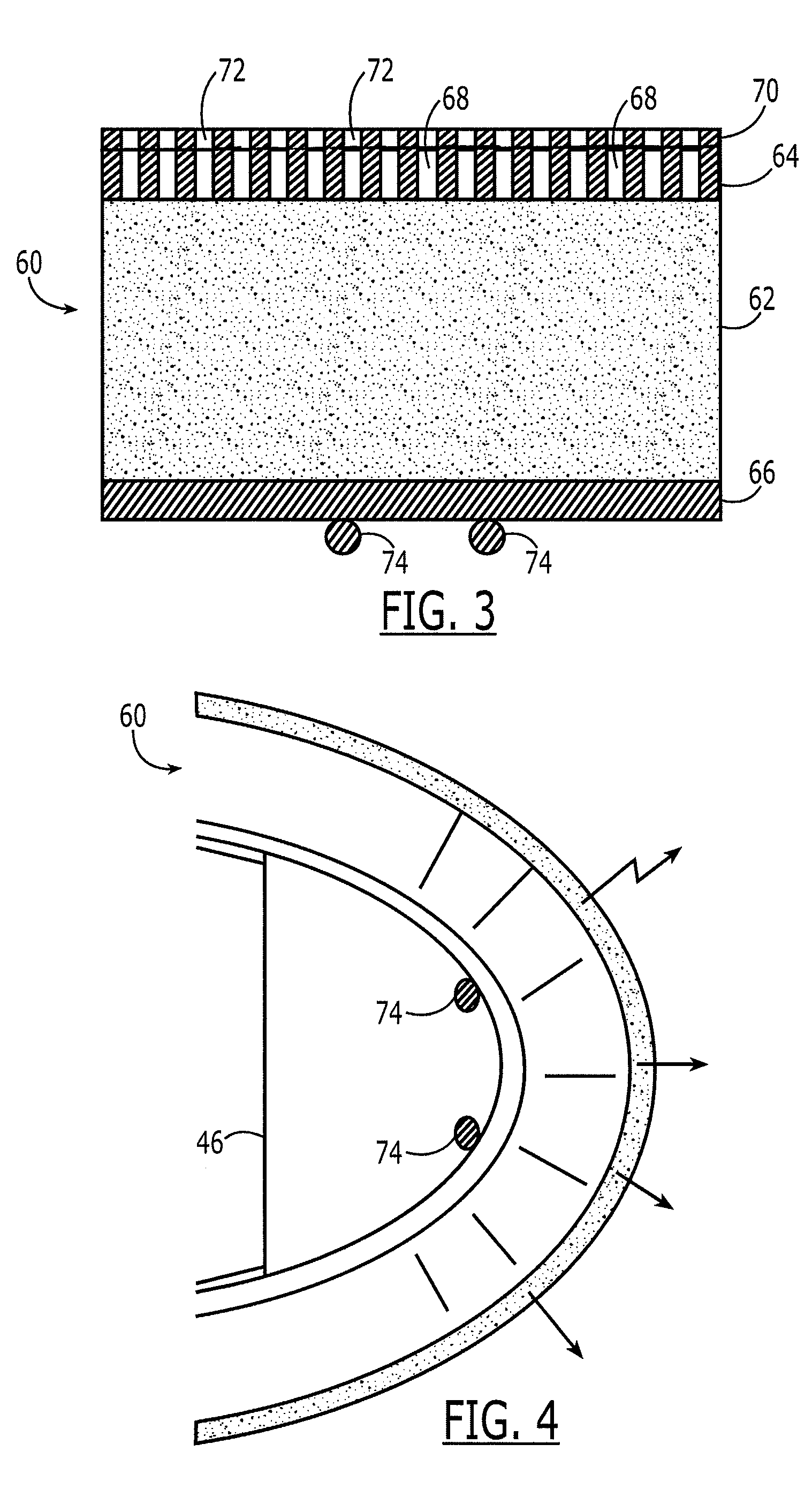
An ice protection system and method are provided that facilitate the prevention or reduction in ice formation upon an aerodynamic surface. The ice protection system may include at least one induction coil spaced apart from an electrically conductive layer of an aerodynamic surface and disposed interior of an exterior surface of the aerodynamic surface. For example, the ice protection system may include a plurality of induction coils with each induction coil being spaced apart from the other induction coils such that the respective induction coils are associated with different portions of the aerodynamic surface. The ice protection system may also include a signal source configured to provide alternating current to the induction coil(s) to thereby generate an electromagnetic field that creates an eddy current in the electrically conductive layer so as to heat the electrically conductive layer.

Description

TECHNOLOGICAL FIELD[0001]Embodiments of the present disclosure relate generally to ice protection systems and methods and, more particularly, to systems and methods for preventing or reducing the icing of an aerodynamic surface.BACKGROUND[0002]Aircraft may be subject to the formation of ice, such as upon the various leading edges, when exposed to icing conditions. Similarly, other aerodynamic surfaces, such as the blades of a wind turbine, may be subject to the formation of ice when exposed to icing conditions. Ice formation upon a leading edge of an aircraft or other aerodynamic surface may have an adverse effect upon the performance of the aircraft, wind turbine or the like. As such, various ice protection systems have been developed to prevent or reduce the formation of ice, at least upon selected aerodynamic surfaces. In this regard, ice protection systems may heat a leading edge or other aerodynamic surface to a temperature above that suitable for ice formation in order to prev...

Claims


Application Information

Patent Timeline
IPC IPC(8): B64D15/12
CPCB64D15/12B64D2033/0233B64D2033/0206
Inventor SAFAI, MORTEZAELANGOVAN, RANGASAMYKHOZIKOV, VYACHESLAV
Owner THE BOEING CO
Learn More