Security system and security tag assembly

a technology which is applied in the field of security system and security tag assembly, can solve the problems of unauthorized personnel, less than totally efficient, useless merchandise, etc., and achieve the effects of facilitating the unauthorized removal of articles, facilitating monitoring and preventing articles from passing, and facilitating the detachment of articles

Active Publication Date: 2018-08-02
ES HLDG DRAGR APS +1
View PDF5 Cites 1 Cited by
  • Summary
  • Abstract
  • Description
  • Claims
  • Application Information

AI Technical Summary

Benefits of technology

[0013]Additionally, the deactivator assembly may include on-off modes of operation which may serve as an additional security feature to prevent the unauthorized use of the deactivator assembly and / or processor. More specifically, authorized personnel associated with the area, retail establishment, etc. may carry or otherwise have immediate access to portable RFID devices, carried on their person. Such portable RFID devices could be in the form of labels, plastic tags, or other RFID operative devices capable of accomplishing the “off-mode” and “on-mode” of the deactivator assembly serving to lock and unlock its use or operability. In use, the portable RFID device carried by authorized personnel will be passed over and RFID antenna associated with the deactivator assembly serving to unlock the deactivator assembly, at least for a preset or preprogrammed time period. Accordingly, when the deactivator assembly isn't used within the preset or preprogrammed period of time it will automatically turn off or be in a locked state of operation. As a result, the next authorized individual intending to complete a checkout procedure will again have to expose or access that individual's portable RFID device to the antenna of the deactivator in order to unlock the deactivator and render it operable. Therefore, the authorized portable RFID devices are structured to place the deactivator assembly and / or processor / POS terminal in an “on-mode” for the predetermined door preset period of time and subsequently upon expiration thereof the deactivator assembly will automatically be disposed in an “off-mode”. In the “on-mode”, the deactivator assembly and / or processor is capable of performing the checkout procedure and / or the deactivation of the RFID component associated with a given security tag assembly, in an intended manner. However, in the “off-mode”, operation of the deactivator assembly is restricted to the extent that a security tag assembly cannot be “deactivated” and / or removed. This will prevent customers or any unauthorized personnel from utilizing the deactivator assembly to deactivate and / or remove a security tag assembly, facilitate its detachment from the article and / or otherwise facilitate the unauthorized removal of the article from the secured area. It is also noted that the plurality of security tag assemblies associated with the security system of the present invention may also be equipped with electronic article surveillance (EAS) of conventional design and operation, to facilitate monitoring and prevention of articles passing through monitoring stations located at exit ways of the secured area. In addition to or instead of the EAS surveillance the security tag assembly may include ink cartridges.
[0017]A cover member is disposed in overlying relation to the RFID label and in covering relation to at least a portion and / or majority of the inner surface of the housing. The cover member serves to retain and accurately position the RFID label in its intended orientation within the housing. Further, structural features associated with the cover member may facilitate its securement to the interior of the housing and / or to the RFID label itself.
[0019]Accordingly, variations of the security system and security tag assembly of the various embodiments of the present invention provide a unique and effective protection of an area to be secured, in terms of preventing unauthorized removal of articles from the secured area.

Problems solved by technology

More specifically, it is believed that such security tag devices serve as a deterrent to unauthorized removal in that a potential thief will recognize that the merchandise will be “stained” or otherwise marked, thereby rendering the merchandise useless, upon forced removal of the security tag.
While popular, it is recognized that a significant number of the anti-theft tags currently being utilized include problems or disadvantages which render them less than totally efficient.
More specifically, wide spread knowledge of the structural features of such security tags allows unauthorized personnel to develop techniques which are specifically designed to remove the tag from the merchandise in a manner which defeats the aforementioned indicator structures.

Method used


Image

  • Security system and security tag assembly
  • Security system and security tag assembly
  • Security system and security tag assembly

Examples


Embodiment Construction

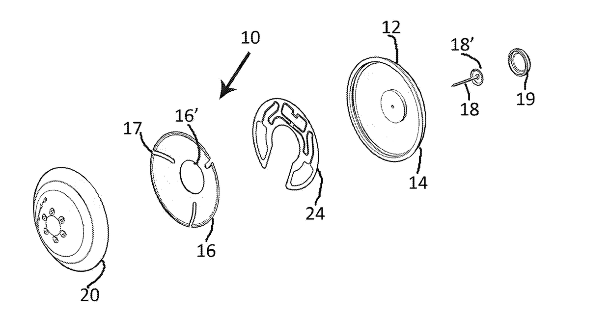
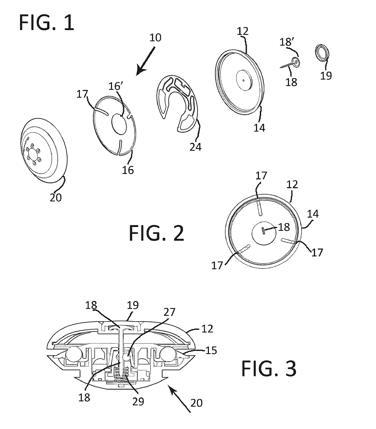
[0039]The present invention is directed to a security system, generally indicated as 100 in FIGS. 10-11, operative to restrict unauthorized removal of articles 101 from an area. Further, at least one, but more practically a plurality of security tag assemblies 10, represented in detail in FIGS. 1-8, are utilized to implement the security system 100.

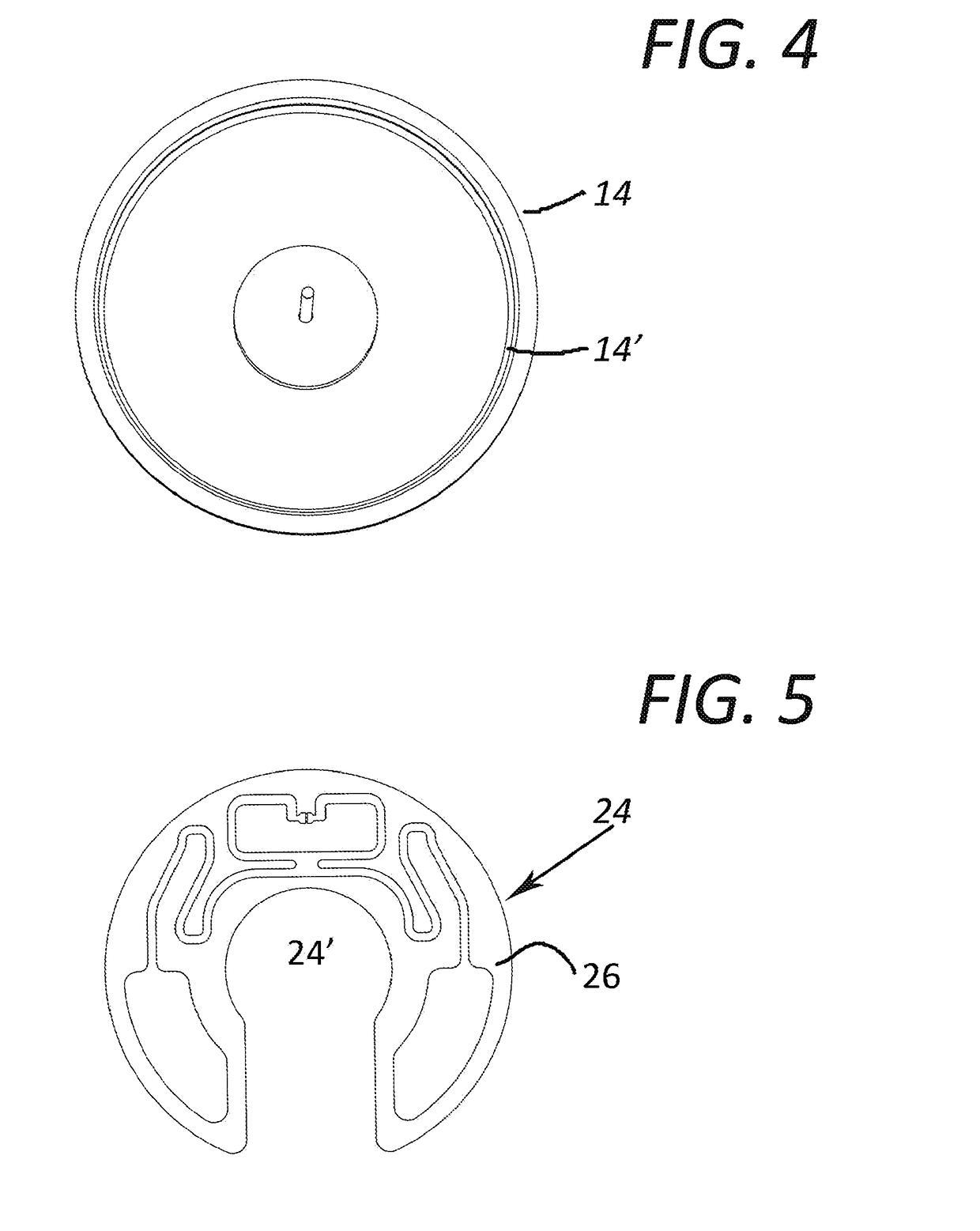
[0040]For purposes of clarity, the structural and operational features of the security tag assembly 10 will be described herein and subsequently its use in the system 100. With primary reference to FIGS. 1-3, the security 10 comprises a tag member 12 including a tag housing 14 and a cover member 16. FIG. 2 represents the housing 14, connector pin 18 and cover member 16 in an assembled orientation, but not connected to a base 20 of the security tag assembly 10. More specifically, the tag member 12 includes an RFID component generally indicated as 24 and represented in detail and in at least partially assembled form in FIGS. 5-6. The RFID c...


PUM


Abstract

A security system and security tag assembly cooperatively operative to restrict unauthorized removal of an article from an area, wherein the security tag assembly is removably attached to the article and includes an RFID component / label configured to encode and retain data associated with the article to which it is attached. A deactivator assembly includes a read component structured to read the article data encoded in the security tag assembly, before or during removal of the tag assembly, wherein the read data is transmitted to a processor for display, storage and / or supplementary processing. One or more portable readers, not associated with the deactivator assembly or processor, are configured to access and display the article data for authorized article control. A review application may be downloaded on communication devices having short range technology and is configured to access the article data to obtain information relating thereto.

Description

CLAIM OF PRIORITY[0001]The present application is a “divisional” patent application of previously filed, now pending application having Ser. No. 15 / 233,020, filed on Aug. 10, 2016, which is based on and a claim of priority is made under 35 U.S.C. Section 119(e) to a provisional patent application that is currently pending in the U.S. Patent and Trademark Office, namely, that having Ser. No. 62 / 334,666 and a filing date of May 11, 2016, and which is incorporated herein by reference.BACKGROUND OF THE INVENTIONField of the Invention[0002]This invention is directed to a security system and security tag assembly incorporating RFID technology, operative to restrict unauthorized removal of articles from an area. Article data is encoded and saved the RFID. A deactivator assembly includes a read component structured to read the encoded article data, wherein the read data is transmitted to a processor for display, storage and / or supplementary processing during or prior to removal of the secur...

Claims


Application Information

Patent Timeline
Patent Type & Authority Applications(United States)
IPC IPC(8): G08B13/24E05B73/00
CPCG08B13/246G08B13/2457G08B13/2454G08B13/2417E05B73/0064G08B13/2434E05B73/0017G06K7/0008G06K19/067
Inventor SKJELLERUP, JOHANSTENILD, EDDIE L.
Owner ES HLDG DRAGR APS
Why Eureka
Try Eureka