Systems and methods for distributed monitoring of remote sites

a distributed monitoring and remote site technology, applied in the field of computer-aided surveillance systems, can solve the problems of difficult single person, difficult for a single person, and event can appear quite different, and the requirement of all locations to be identical is not practical, so as to achieve the effect of ensuring the safety of the environmen

Active Publication Date: 2007-12-06
JOHNSON CONTROLS TYCO IP HLDG LLP
View PDF5 Cites 169 Cited by
  • Summary
  • Abstract
  • Description
  • Claims
  • Application Information

AI Technical Summary

Benefits of technology

[0009]Accordingly, in a first aspect, the invention provides a method for facilitating monitoring multiple disparate sites that includes providing a set of rules describing events of interest. The rules have multiple components, some of which are site-specific components, whereas other components are site-independent. The site-independent components are defined globally and the rules are then distribute at the multiple sites, thereby facilitating the definition of the site-specific components and the monitoring of the site using the rules.

Problems solved by technology

However, because of non-standard floor-plans, variable camera configurations, and other site differences, the occurrence of an event can appear quite different (from the point-of-view of a surveillance system) at each location.
Such differences make it difficult for a single person (e.g., a chief security officer or corporate marketing analyst) to specify an event at the level of detail needed in order to reliably detect the event at multiple disparate locations.
Although this approach allows a global operator to centrally define events of interest and replicate the events across all locations, requiring all locations to be identical is not practical.
A third approach places the responsibility of event definition in the hands of local site operators, but such an approach relinquishes any element of centralized control and significantly reduces data consistency across sites.
Unfortunately, none of these approaches is sufficient.
In some cases the web server governs access granted to the remote clients, restricting them, for example, such that they can only modify site-specific components or access a subset of the components.

Method used


Image

  • Systems and methods for distributed monitoring of remote sites
  • Systems and methods for distributed monitoring of remote sites
  • Systems and methods for distributed monitoring of remote sites

Examples


Embodiment Construction

[0029]Although described herein with reference to tracking patrons and products within retail establishments, and as useful when implemented with regard to detecting theft and measuring various merchandising and operational aspects of stores, the systems and techniques described below are equally applicable to any environment being monitored, such as airports, casinos, schools, amusement parks, entertainment venues, and office buildings for a wide range of purposes.

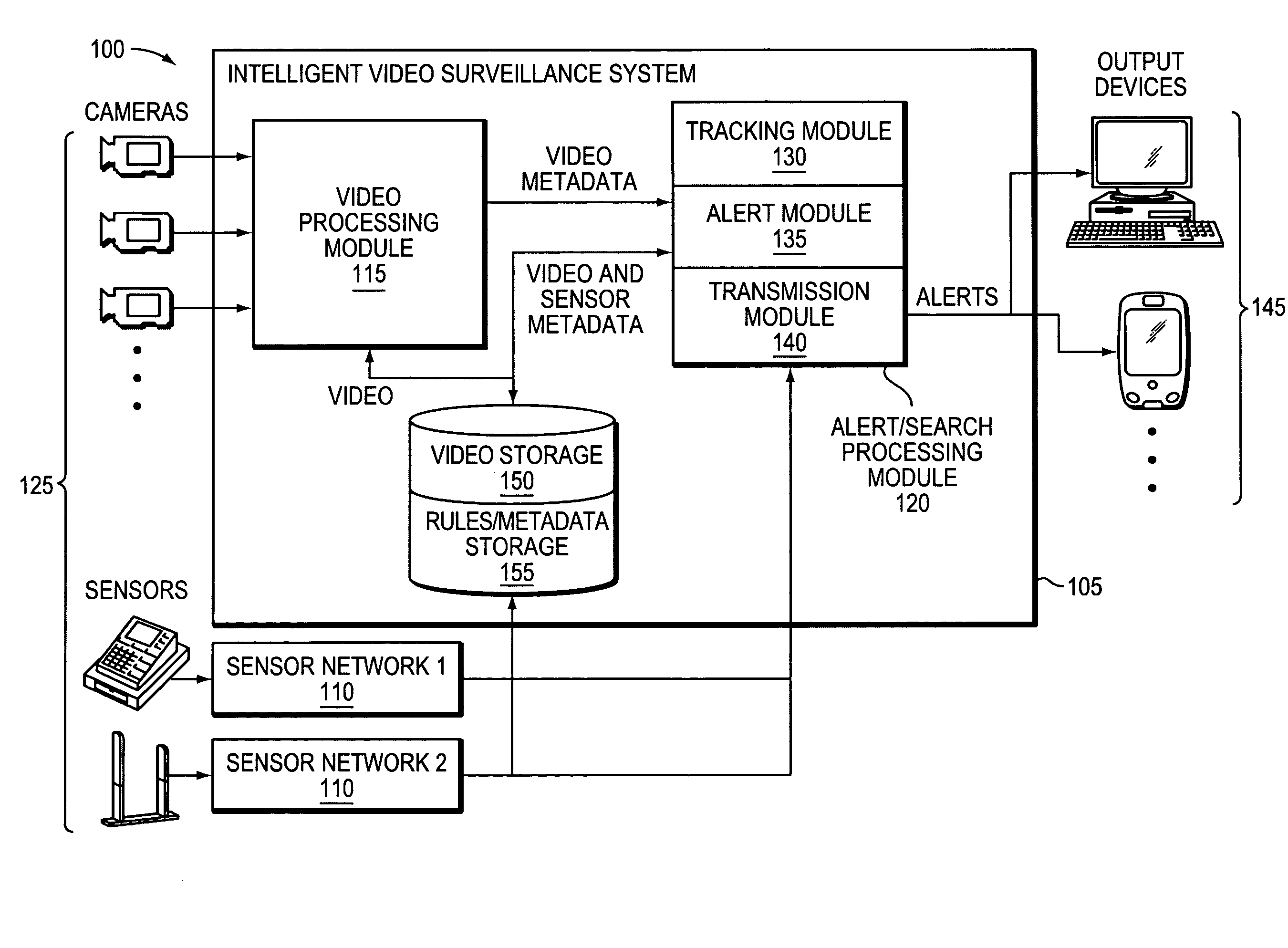
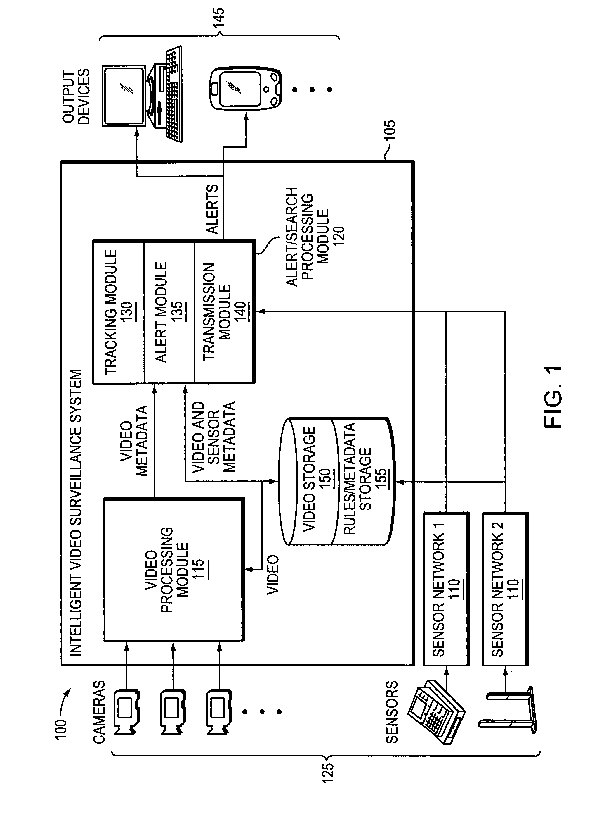
[0030]FIG. 1 illustrates an integrated video surveillance and sensor network system 100 in accordance with various embodiments of the invention. The system 100 captures surveillance data from any number of monitoring devices within one or more monitored sites, the data thus being available for analysis and / or processing locally (at each monitoring device, at a local processor or both), at a single centralized location and / or at any number of intermediate data processing locations. In some embodiments, the processing and a...


PUM


Abstract

Rules are applied to video surveillance data to detect events. Localization of the events is achieved by decomposing events into distinct components, each of which can, in some embodiments, be defined at different locations and by different users.

Description

TECHNICAL FIELD[0001]This invention relates to computer-based methods and systems for monitoring activities, and more specifically to a computer-aided surveillance system capable of detecting events occurring at multiple sites.BACKGROUND INFORMATION[0002]The current heightened sense of security and declining cost of monitoring equipment have resulted in increased use of surveillance systems using technologies such as closed-circuit television (CCTV). Such systems have the potential to reduce crime, prevent accidents, and generally increase security in a wide variety of environments. Video surveillance systems typically include a series of cameras placed in various locations about an area of interest (e.g., a warehouse, a retail establishment, an office building, an airport, for example). The cameras transmit video feeds back to a central viewing stations (or multiple stations), typically manned by a security officer. The various surveillance feeds are displayed on a series of screen...

Claims


Application Information

Patent Timeline
Patent Type & Authority Applications(United States)
IPC IPC(8): G08B19/00G08B1/00
CPCG08B13/19615G08B13/19697G08B13/19671G08B13/19645
Inventor BUEHLER, CHRISTOPHER J.
Owner JOHNSON CONTROLS TYCO IP HLDG LLP
Why Eureka
Try Eureka