Organic electroluminescent panel, organic electroluminescent display, organic electroluminescent lighting device, and production methods thereof

a technology of organic electroluminescent panels and lighting devices, applied in the manufacture of electrode systems, electric discharge tubes/lamps, discharge tubes luminescent screens, etc., can solve the problems of increased aperture ratio, difficult to provide, and reduced thickness of panels, so as to reduce heating time and simplify processes. , the effect of reducing the thickness

Active Publication Date: 2011-12-27
SHARP KK
View PDF29 Cites 2 Cited by
  • Summary
  • Abstract
  • Description
  • Claims
  • Application Information

AI Technical Summary

Benefits of technology

[0011]The present inventor made various investigations of an organic EL panel including an element substrate, a sealing substrate facing the element substrate, and an organic EL element arranged on the sealing substrate side of the above-mentioned element substrate. The inventor noted a configuration of a member (sealing member) that is arranged to seal the organic EL element. Then the inventor discovered the following. A space and the like are hardly generated between the second sealing member and the respective substrates even if the substrates are deformed due to environmental temperature changes and the like, and as a result, moisture and the like can be prevented from entering the inside of the organic EL element when the organic EL panel has the following configuration: the first sealing member for sealing a gap between the element substrate and the sealing substrate and the second sealing member for covering the organic EL element are arranged; the first sealing member and the second sealing member are arranged with a space therebetween. The inventor also discovered the following. If the space between the first sealing member and the second sealing member is under a vacuum or reduced pressure condition, gas inside the organic EL panel can be kept inside that space. So it is possible to prevent the organic EL element from being deteriorated by such gas. That is, the inventor discovered that the organic EL element can maintain stable light emission characteristics for a long period of time if the first sealing member and the second sealing member are arranged with a space therebetween and the space between the first sealing member and the second sealing member is under a vacuum or reduced pressure condition. As a result, the above-mentioned problems can be admirably solved, leading to development and completion of preferred embodiments of the present invention.
[0055]According to the organic EL panel of various preferred embodiments of the present invention, even if the substrate is warped by external stress, for example, the space between the first sealing member and the second sealing member functions as a buffer, and so separation of the second sealing member (sealing film) formed inside the organic EL panel can be prevented, for example. As a result, moisture and the like can be prevented from reaching the organic EL element. The space between the first sealing member and the second sealing member is in a vacuum or reduced pressure state, and so gas inside the organic EL panel can be kept inside the space. Accordingly, deterioration of the light-emitting layer of the organic EL element, and the like, due to such gas, can be prevented. Hence, the organic EL panel according to various preferred embodiments of the present invention can maintain stable light emission characteristics for a long period of time.

Problems solved by technology

However, it is difficult to provide the organic EL panel having this sealing can structure with a top-emission structure because in the top-emission structure, light is outputted from an upper surface of the panel (i.e., an increase in aperture ratio is difficult), and further, a reduction in thickness of the panel is also difficult.
If air bubbles are generated inside the adhesive, the air bubbles might deteriorate the organic EL element.
The sealing resin is surrounded and sealed by the protective barrier although the sealing resin generates a great amount of gas when being cured, and so the generated gas deteriorates the organic EL element, and a non-light-emitting region, what is called dark spot, is generated, and as a result, the light emission cannot be maintained.
In addition, if an organic EL element that includes only a solid sealing resin as a member for sealing an organic EL element is used as an organic EL element having a top-emission structure, as in Japanese Kokai Publication No. 2006-179352, the solid sealing resin needs to have transparency, and so the solid sealing resin cannot include spacers and the like.
So, it is difficult to keep a thickness (gap between the substrates) or pattern shape of the solid sealing resin constant, and uneven display that is caused by a variation in characteristics or interference fringes, due to transmittance change, is generated.

Method used


Image

  • Organic electroluminescent panel, organic electroluminescent display, organic electroluminescent lighting device, and production methods thereof
  • Organic electroluminescent panel, organic electroluminescent display, organic electroluminescent lighting device, and production methods thereof
  • Organic electroluminescent panel, organic electroluminescent display, organic electroluminescent lighting device, and production methods thereof

Examples


embodiment 1

Preferred Embodiment 1

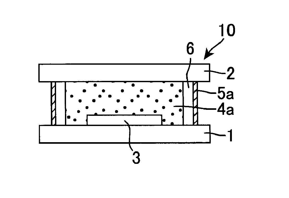
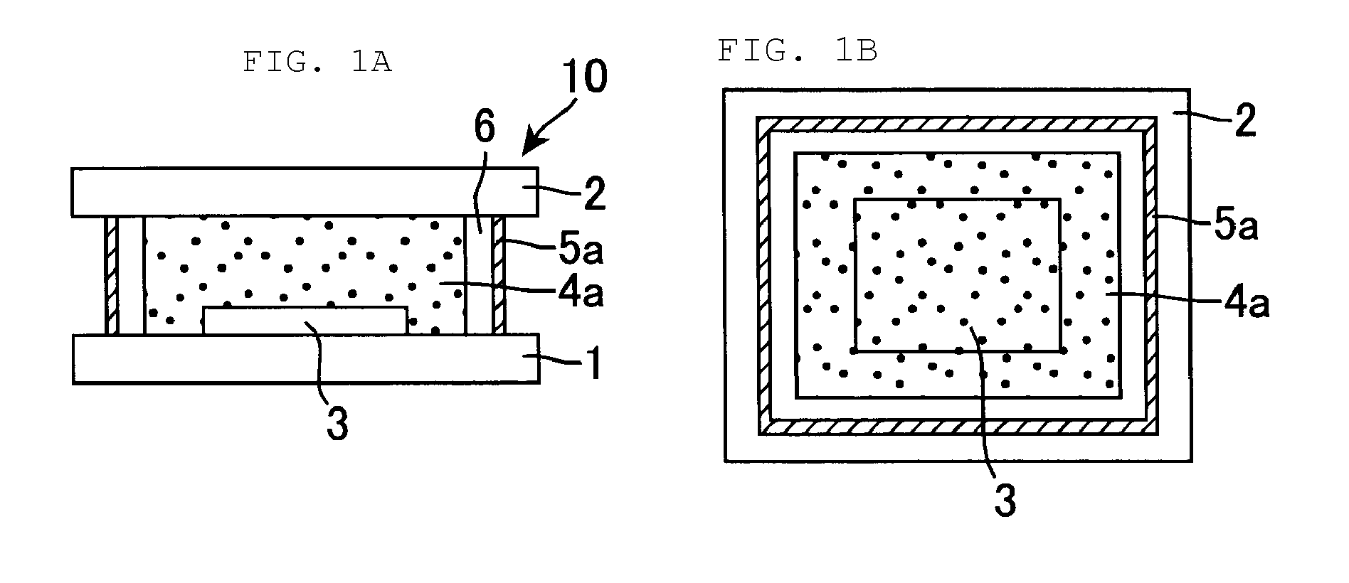
[0067]FIG. 1A is a cross-sectional view schematically showing a configuration of an organic EL panel in accordance with Preferred Embodiment 1. FIG. 1B is a schematic plan view thereof.

[0068]As shown in FIGS. 1A and 1B, an organic EL panel 10 in accordance with Preferred Embodiment 1 preferably includes: a flat element glass (element substrate) 1; a flat sealing glass (sealing substrate) 2 facing the element glass 1; an organic EL element 3 arranged on the sealing glass 2 side of the element glass 1; a cured product (the first sealing member) 5a of a liquid sealing member (airtight seal, liquid adhesive) arranged to seal a gap between the element glass 1 and the sealing glass 2; a cured product (the second sealing member) 4a of a solid sealing member that is arranged to cover the organic EL element 3 and that forms a vacuum or reduced pressure space 6 between itself and the cured product 5a of the liquid sealing member. In FIGS. 1A and 1B, only one organic EL e...

embodiment 2

Preferred Embodiment 2

[0096]FIGS. 3A to 3D are perspective views schematically showing production steps of an organic EL panel in accordance with Preferred Embodiment 2.

[0097]The sealing glass (sealing substrate) 2 is produced first, as shown in FIG. 3A.

[0098]Then, although not shown in FIG. 3A, a plurality of organic EL elements are arranged on the element glass (element substrate).

[0099]Then the solid sealing member 4 is arranged on the sealing glass 2 by roll-to-roll method, as shown in FIG. 3B (solid sealing member-arranging step). The solid sealing member 4 is arranged in such a way that it covers a plurality of organic EL elements 3 after the element glass 1 is attached to the sealing glass 2. Thus, the plurality of organic EL elements 3 are covered by a common solid sealing member 4, and thereby the takt time for the attachment of the solid sealing member 4 can be significantly shortened compared to the case that the organic EL elements 3 are each covered by different solid s...

embodiment 3

Preferred Embodiment 3

[0105]FIG. 5A is a cross-sectional view schematically showing a state that a liquid sealing member including spacers is arranged on an element glass. FIG. 5B is a cross-sectional view schematically showing a state that the glass substrate 1 is attached to the sealing glass 2 after the state shown in FIG. 5A.

[0106]The present Preferred Embodiment is preferably the same as Preferred Embodiment 1, except that the element glass 1 is attached to the sealing glass 2 as shown in FIG. 5B, after the liquid sealing member 5 including spherical spacers 7 is arranged on the element glass 1 as shown in FIG. 5A. The average particle size of the spacer 7 is preferably about 1 μm to about 100 μm, and it is more preferably about 20 μm or less, for example, in view of sealing performances and light transmittance. Thus, the spacers 7 are included in the liquid sealing member 5, and thereby, a gap between the element glass 1 and the sealing glass 2 can be kept constant. In this ca...


PUM

PropertyMeasurementUnit
thicknessaaaaaaaaaa
light transmittanceaaaaaaaaaa
pressureaaaaaaaaaa

Abstract

An organic electroluminescent panel, an organic electroluminescent display, an organic electroluminescent lighting device, each include an organic electroluminescent element that maintains stable light emission characteristics for a long period of time. The organic electroluminescent panel includes an element substrate; a sealing substrate facing the element substrate; and an organic electroluminescent element disposed on a sealing substrate side of the element substrate, wherein the organic electroluminescent panel further includes a first sealing member and a second sealing member, the first sealing member sealing a gap between the element substrate and the sealing substrate, the second sealing member covering the organic electroluminescent element, the first sealing member and the second sealing member being arranged with a space therebetween, the space is in a vacuum or reduced pressure state.

Description

BACKGROUND OF THE INVENTION[0001]1. Field of the Invention[0002]The present invention relates to an organic electroluminescent (EL) panel, an organic EL display, an organic EL lighting device, and production methods thereof. More particularly, the present invention relates to an organic EL panel that can be preferably used in an organic EL display or an organic EL lighting device, and to an organic EL display, an organic EL lighting device, and production methods thereof.[0003]2. Description of the Related Art[0004]According to a conventional organic EL panel, deterioration of an organic EL element, caused by the organic EL element being exposed to oxygen, moisture, and the like, is prevented by the following sealing can structure commonly used: a desiccant is attached to a sealing can (concave glass can) and a sealing resin is arranged into a frame shape to surround an organic EL element. However, it is difficult to provide the organic EL panel having this sealing can structure wit...

Claims


Application Information

Patent Timeline
Patent Type & Authority Patents(United States)
IPC IPC(8): H01L51/50
CPCH01L51/5237H10K59/8723H10K59/8722H10K50/8428H10K50/8426
Inventor OTA, YOSHIFUMI
Owner SHARP KK
Why Eureka
Try Eureka