Crossbow

a crossbow and crossbow technology, applied in the field of archery devices, can solve the problems of large storage space, crossbows with stock and transverse limbs, and safety concerns, and achieve the effects of reducing the risk of injury, reducing the safety of use, and increasing the risk of injury

Inactive Publication Date: 2012-01-10
KODABOW
View PDF57 Cites 70 Cited by
  • Summary
  • Abstract
  • Description
  • Claims
  • Application Information

AI Technical Summary

Benefits of technology

[0020]In accordance with embodiments of the present disclosure, a crossbow is provided including a stock having a fore end, a limb for engaging a bowstring of the crossbow and maintaining a bowstring of the crossbow in a tensioned state, the limb being moveably coupled to the stock in a vicinity of the fore end such that the limb is adapted to be rotated outward from a relatively collapsed position relative to the stock, toward and into a shooting position relative to the stock, and a finger moveably coupled to the stock in a vicinity of the fore end such that the finger is capable of being rotated relative to the stock, the finger further being adapted, via the finger so rotating relative to the stock, to engage and impart an urging force to the limb, and to thereby rotate the limb outward from a relatively collapsed position relative to the stock toward the shooting position relative to the stock.

Problems solved by technology

As target and sport archery increases in popularity, several shortcomings of the standard archery equipment limit many users and lead to safety concerns for all.
The basic crossbow form, with a stock and transverse limbs, can be bulky and difficult to store and transport.
A case for storing and transporting the crossbow may be determined by the shape of the crossbow, and as such may require a considerable amount of storage space, and may be awkward to carry and move from place to place.
A crossbow having fixed limbs and a stock may be stored or transported in a pre-loaded state, with its bowstring strung between the limbs, avoiding the time and effort required for reassembly, but potentially creating safety concerns and / or elevated component wear over time due to the presence of a continuous preload in the bowstring and the limbs.
A crossbow having fixed limbs and a stock may alternatively be stored or transported in an unloaded state (e.g., without a bowstring), allowing relaxation of the limbs during periods of non-use and transport, but potentially requiring a great deal of effort to string the crossbow each time the crossbow is retrieved prior to use.
This task can also be quite strenuous, generally requiring the user to generate a large amount of force.
Either way, manual cocking of a crossbow requires a user to generate considerable force, which can quickly become tiring, especially when attempted repeatedly during the course of a hunt.
While plainly useful for completing the strenuous final state of drawing back the bowstring, such a crank assembly can add considerable weight and / or bulk to the crossbow.
Unfortunately, however, the same advanced state of firing readiness in the trigger mechanism can tend to leave the crossbow vulnerable to so-called ‘dry fire’, in which a cocked bowstring of the crossbow is unintentionally released prior to a bolt being loaded in the crossbow, such that the time and effort needed to cock the crossbow in the first place must now be repeated.
More particularly, after the crossbow has been cocked, but before the crossbow has been loaded with a bolt as described above, the trigger mechanism may be vulnerable to inadvertent actuation, normally leading to an unintended release of the bowstring from the trigger mechanism.
However, even when working as intended, the stop mechanism not only still fails to prevent dry fire, but also requires the bowstring to be redrawn to at least some extent backward along the stock and back into engagement with the trigger mechanism to restore the crossbow to the fully cocked state.
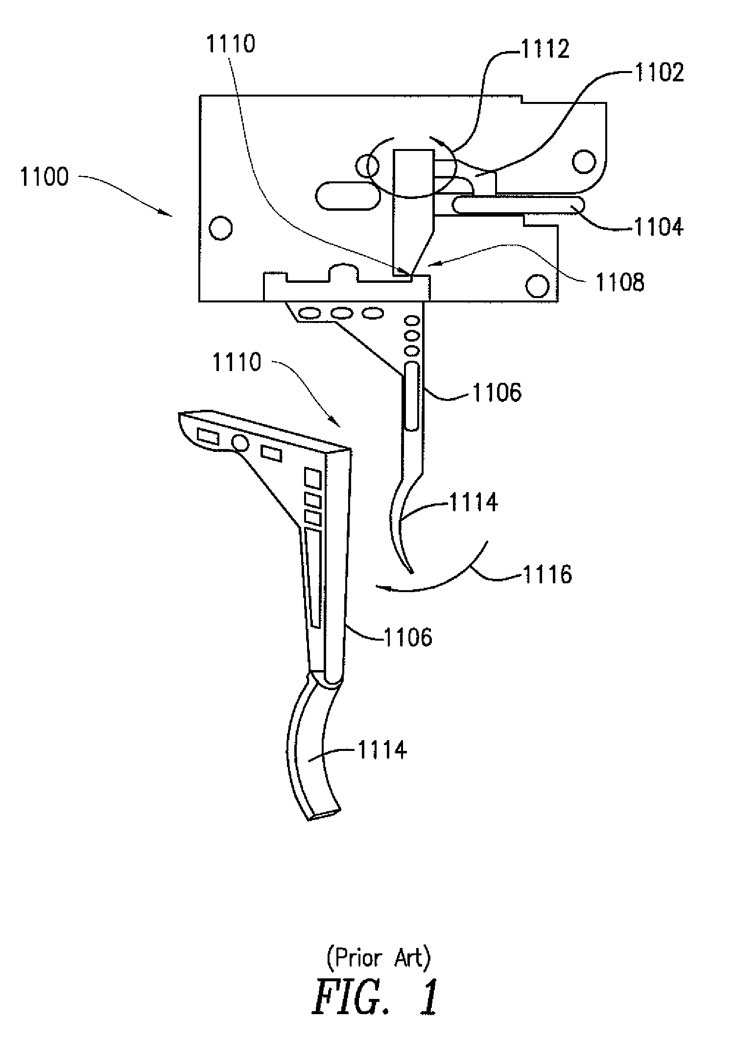
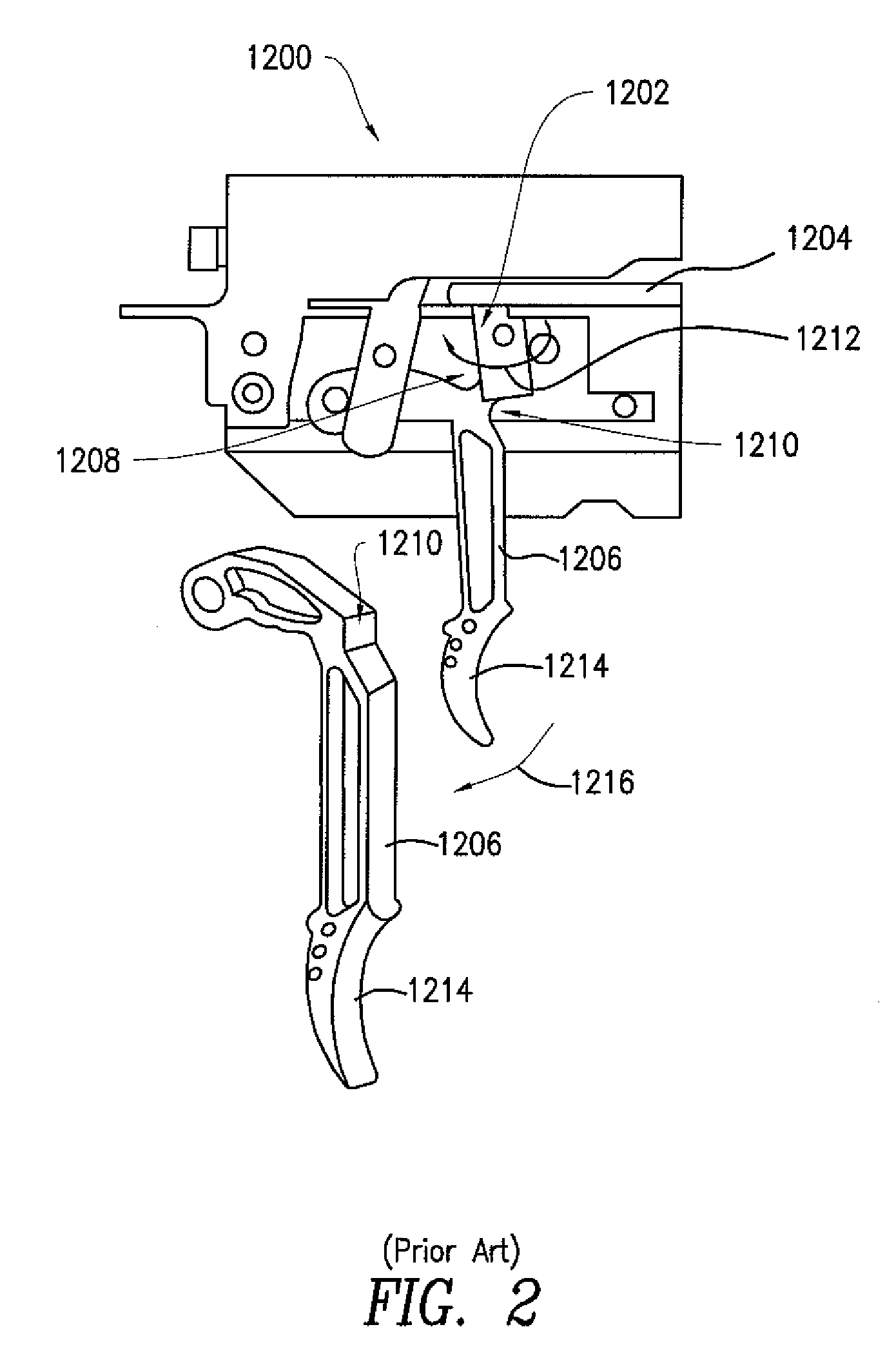
While this may beneficially reduce the required rotational throw of the trigger blade 1114, 1214, 1314 to a minimum extent, and perhaps enhance the overall precision of the instrument, such an arrangement unfortunately also tends to result in an elevated contact pressure between the reaction surfaces involved.

Method used


Image

  • Crossbow
  • Crossbow
  • Crossbow

Examples


Embodiment Construction

[0032]Referring now to FIG. 4, a crossbow 1400 in accordance with embodiments of the present disclosure is partially shown, in top view. The crossbow 1400, which in FIG. 4 exhibiting a shooting configuration, may have a fore end 1402 and a rear end 1404, and may include a gripper 1406 positioned in a vicinity of the rear end 1404, a stock 1408 coupled to extending from the gripper 1406 and toward the fore end 1402, and limbs 1410 coupled to the stock 1408, at respective sides 1412, 1414 thereof, and in a vicinity of the fore end 1402. As will be described below, the crossbow 1400 may further include a limb support mechanism 1416 via which the limbs 1410 may be both moveable and selectively collapsible relative to the stock 1408. As will also be described below the crossbow 1400 may include a limb actuator 1418, the limb actuator 1418 being interoperable with the limb support mechanism 1416 for permitting a user of no greater than average strength to quickly and easily selectively ca...


PUM


Abstract

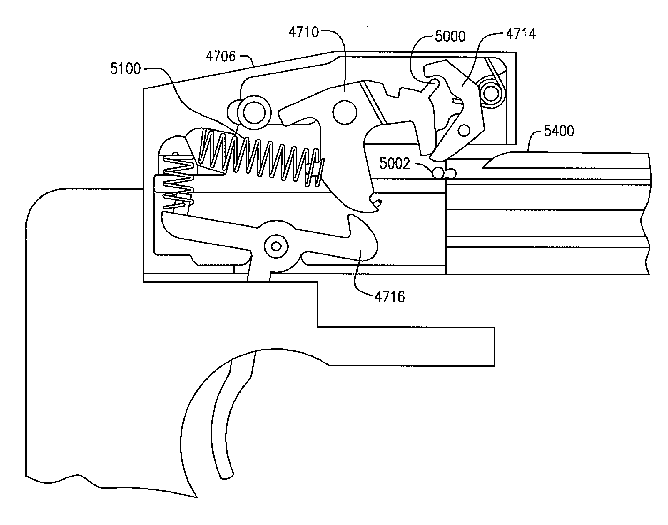
A crossbow includes a trigger mechanism having a trigger housing for receiving a bowstring of a crossbow and a bowstring catch mounted with respect to the housing and adapted to releasably engage a crossbow bowstring brought within the trigger housing. The crossbow further includes a trigger adapted to releasably engage the bowstring catch, the trigger being further adapted to be selectively actuated by a user so as to cause the trigger to release the bowstring catch, thereby causing the bowstring catch to release a crossbow bowstring. Optionally, the crossbow may include a ball disposed between the bowstring catch and the trigger, the ball being adapted to bear and react to forces arising between the bowstring catch and the trigger during at least one of the trigger so engaging the bowstring catch and the trigger so releasing the bowstring catch.

Description

FIELD OF THE INVENTION[0001]The present disclosure is directed to an archery device. More particularly, the present disclosure is directed to a crossbow having at least one of a cocking mechanism, a trigger mechanism, a dry-fire prevention mechanism, and a hinged-limb mechanism.BACKGROUND OF THE INVENTION[0002]As target and sport archery increases in popularity, several shortcomings of the standard archery equipment limit many users and lead to safety concerns for all. In order to improve the experience and safety, improvements to the standard equipment in the areas of transporting and assembling the crossbow, drawing back the bowstring, releasing the bowstring, and preventing dry-fires are needed.[0003]The basic crossbow form, with a stock and transverse limbs, can be bulky and difficult to store and transport. A case for storing and transporting the crossbow may be determined by the shape of the crossbow, and as such may require a considerable amount of storage space, and may be a...

Claims


Application Information

Patent Timeline
Patent Type & Authority Patents(United States)
IPC IPC(8): F41B5/12
CPCF41B5/12F41B5/1469F41C23/04
Inventor MATASIC, CHARLES S.ABEL, BARON E.PATEL, SUJAN V.WOLFGANG, JR., CURVIN L.
Owner KODABOW
Why Eureka
Try Eureka