
Thickness detector of paper

a thickness detector and paper technology, applied in the direction of thin material processing, instruments, article separation, etc., can solve the problems of inability to accurately detect thickness, difficulty in setting the operation of the gap d between the detection roller b>102/b> and the reference roller b>101/b>, and often out of order gap d during use, so as to reduce the kick in the output waveform

Active Publication Date: 2012-01-10
GLORY KOGYO KK
View PDF25 Cites 6 Cited by
  • Summary
  • Abstract
  • Description
  • Claims
  • Application Information

AI Technical Summary

Benefits of technology

The present invention provides a paper-sheet-thickness detecting device for a cash handling machine that can accurately detect the thickness of banknotes without being affected by the setting of the detection roller. The device includes a reference roller and a plurality of detecting units with detection rollers and detection blocks, which are arranged along a fulcrum shaft. A holding block holds at least the fulcrum shaft. The detection roller is provided to face and come into contact with the reference roller, and the detection block has a first end at which the detection roller is provided and a second end which is rotatably fixed around the fulcrum shaft so that the detection block is rotated and displaced when a paper sheet passes through. The device can accurately detect the thickness of a paper sheet and detect a taped part on the sheet without requiring fine adjustment of the detection roller. The device simplifies the configuration of the detection roller by configuring the biasing unit and the detector by one member.

Problems solved by technology

In the conventional technique, however, a setting operation of the gap d between the detection roller 102 and the reference roller 101 becomes quite difficult.
Further, even if the gap d can be accurately set, the gap d may often go out of order during use.
However, if the detection roller is always brought into contact with the reference roller, a tremor (pitching) of the detection roller occurs during passage of a paper sheet, thereby causing a problem such that the thickness cannot be detected accurately.
Further, when the paper sheet passes through between the detection roller and the reference roller, fine dust adhered to the surface of the paper sheet adheres to the detection roller and the reference roller, and if the roller is coated with the dust, accurate detection cannot be performed.
However, if the scraper is secured to a part of an apparatus, even in the case of an elastic scraper, a movement of a detection roller when a banknote comes in between the rollers is blocked due to an end of the scraper, and thus accurate thickness detection cannot be performed.
Furthermore, there is such a problem that paper jam occurs due to a resistance when the paper sheet bumps against the detection roller.

Method used


Image

  • Thickness detector of paper
  • Thickness detector of paper
  • Thickness detector of paper

Examples


Embodiment Construction

[0028]A paper-sheet-thickness detecting device according to the present invention will be explained below in detail with reference to the accompanying drawings.

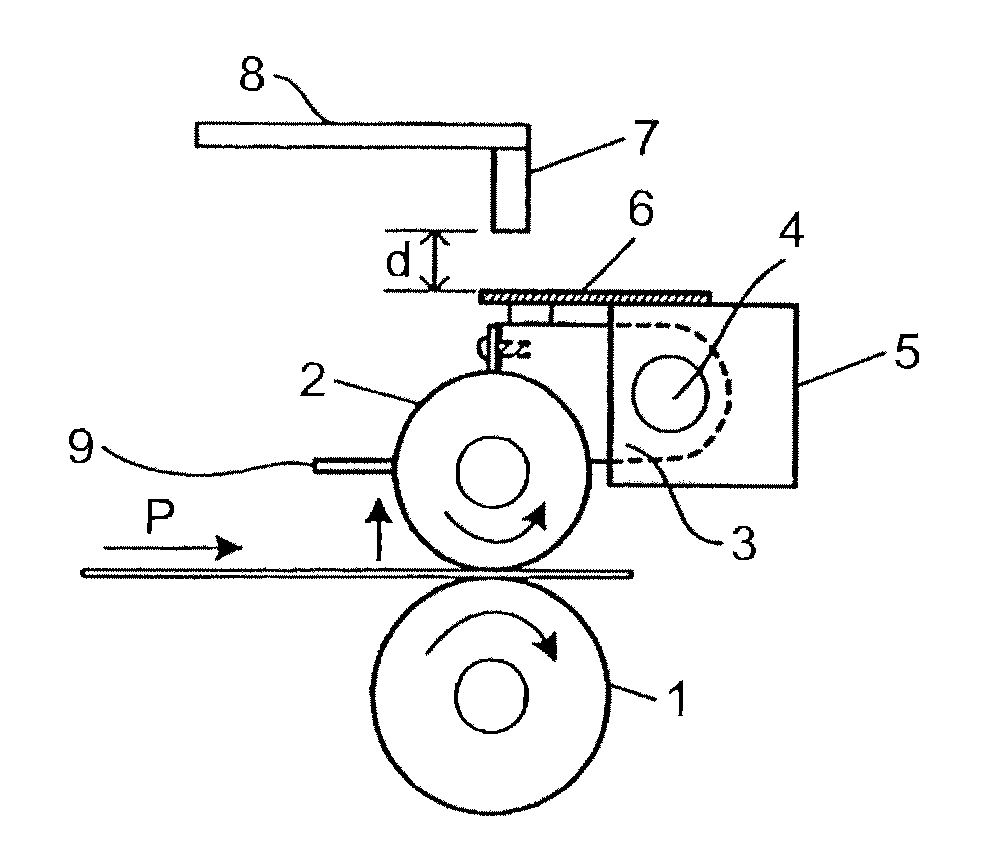
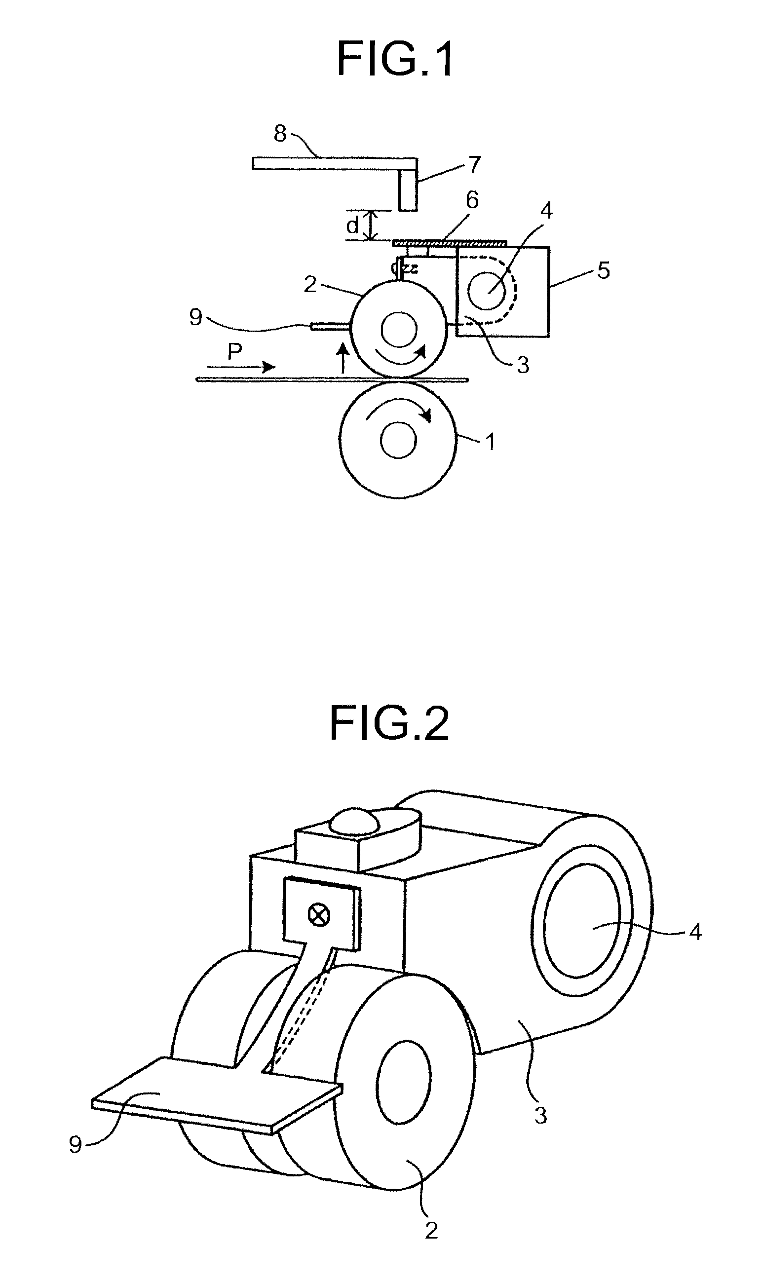
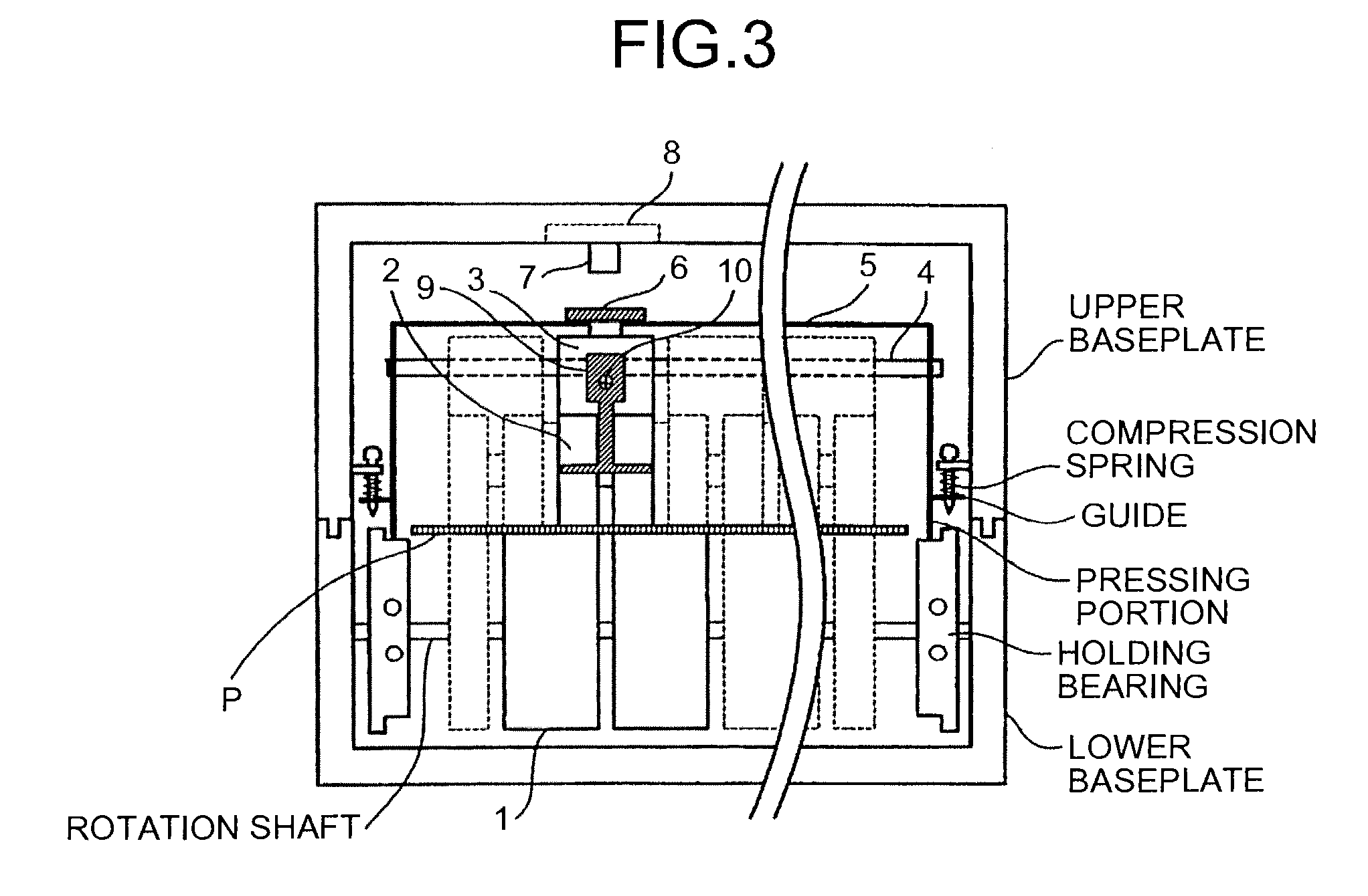
[0029]FIG. 1 is an explanatory diagram of a principle of thickness detection by the paper-sheet-thickness detecting device according to the present invention. The thickness detecting device includes a reference roller 1 with a rotation shaft being fixed, which serves as a reference position of thickness, a detection roller 2 provided to come into contact with the reference roller 1, a detection block 3 in which the detection roller 2 is provided at one end and the other end thereof is rotatably fixed around a fulcrum shaft 4 so that the detection block 3 is rotated and displaced in a direction of the arrow according to a thickness of the paper sheet P passing through between the reference roller 1 and the detection roller 2, a holding block 5 that holds at least the fulcrum shaft 4 of the detection block 3, a plate spring 6 m...


PUM


Abstract

A paper-sheet-thickness detecting device includes a reference roller provided on a fixed rotation shaft; a detection roller provided to face and come into contact with the reference roller; a detection block in which the detection roller is provided at one end and the other end is rotatably fixed around a fulcrum shaft so that the detection block is turned and displaced according to a thickness of a paper sheet passing through between the reference and detection rollers; a holding block that holds the fulcrum shaft; a first pressing member fixed to the holding block to maintain contact between the detection and reference rollers by pressing the detection block, the first pressing member being displaced according to rotation and displacement of the detection block when the paper sheet passes through between the reference and detection rollers; and a displacement detector that detects a displacement amount of the first pressing member.

Description

TECHNICAL FIELD[0001]The present invention relates to a paper-sheet-thickness detecting device incorporated in a banknote recognition unit in a cash handling machine installed at a bank or the like to detect thickness of banknotes.BACKGROUND ART[0002]In an apparatus that handles banknotes, such as a banknote recognition unit provided in a cash handling machine or the like and an automatic vending machine, it is important to recognize a banknote altered by a tape, paper or the like, and the banknote recognition unit is provided for the recognition.[0003]The banknote altering techniques have been sophisticated particularly in recent years. For example, banknotes, securities, stamps, and checks altering by a tape, paper, or seal have been circulated.[0004]As an example of a banknote judgment unit that authenticates banknotes or the like altered by a tape, paper or the like, there is a conventional technique described in Japanese Utility Model Application Laid-open No. H6-49442, for exa...

Claims


Application Information

Patent Timeline
Patent Type & Authority Patents(United States)
IPC IPC(8): B65H7/02G06K9/00G07D7/00G07D7/16G07D7/164G07D7/189
CPCB65H7/02G07D7/164B65H2404/14B65H2511/13B65H2511/162B65H2515/842B65H2553/61B65H2701/1912B65H2220/09B65H2220/03B65H7/12B65H2404/1421B65H2404/1521B65H2511/22B65H2511/16B65H2515/84B65H2220/01
Inventor MURANAKA, MITSUHIKOOGAWA, KAZUHITO
Owner GLORY KOGYO KK
Learn More