Surgical sagittal saw blade with angled teeth and chip catchment and reciprocating saw blade with broached teeth

a saw blade and sagittal technology, applied in the field of surgical saw blades, can solve the problems of reducing affecting the limitations of the known varieties so as to improve the cutting efficiency of the saw blade, reduce the kick generated by the blade, and increase the blade stability

Active Publication Date: 2007-05-31
STRYKER EURO OPERATIONS HLDG LLC
View PDF17 Cites 64 Cited by
  • Summary
  • Abstract
  • Description
  • Claims
  • Application Information

AI Technical Summary

Benefits of technology

[0006] This invention relates to new and useful saw blades. Specifically, this invention is related to a sagittal saw blade with teeth arranged so, from the opposing side edges of the blade, the teeth are disposed inwardly relative to each other. This feature of the saw blade of this invention reduces the kick generated by the blade each time the blade cuts against a section of bone. The reduction of kick increases blade stability.
[0007] The sagittal saw blade of this invention is further constructed so that the blade body defines a void space behind the blade teeth. The void space functions as a catchment into which the bone chips formed during the cutting process flow. Since the bone chips flow into the catchment, the chips do not build up in the space between the blade teeth and the bone being cut. The minimization of bone chip build up along this interface improves the cutting efficiency of the blade.
[0008] The reciprocating saw blade of this invention is designed so that the blade teeth are arranged in a pattern that is not parallel to longitudinal axis of the blade body. An advantage of the angled relationship of the blade teeth of this invention is that, during a single cutting motion, the later teeth cutting the bone are in a deeper position. This increases the amount of material these later teeth are able to remove. Thus, the tooth pattern of the reciprocating saw blade of this invention improves the cutting efficiency of the blade.

Problems solved by technology

Nevertheless, there are limitations associated with the known varieties of both these blades.
In particular, when a sagittal saw blade is pressed against bone in a cutting procedure, the blade can become unstable.
The presence of these chips reduces the cutting efficiency of the saw.
Further, reciprocating saw blades are similarly known to their own inefficiencies.

Method used


Image

  • Surgical sagittal saw blade with angled teeth and chip catchment and reciprocating saw blade with broached teeth
  • Surgical sagittal saw blade with angled teeth and chip catchment and reciprocating saw blade with broached teeth
  • Surgical sagittal saw blade with angled teeth and chip catchment and reciprocating saw blade with broached teeth

Examples


Embodiment Construction

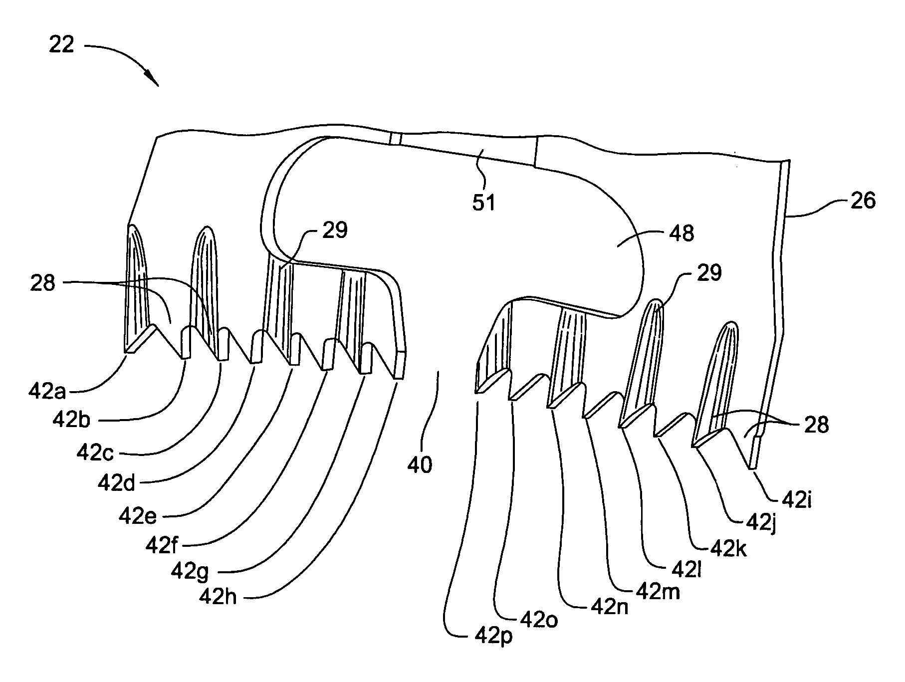
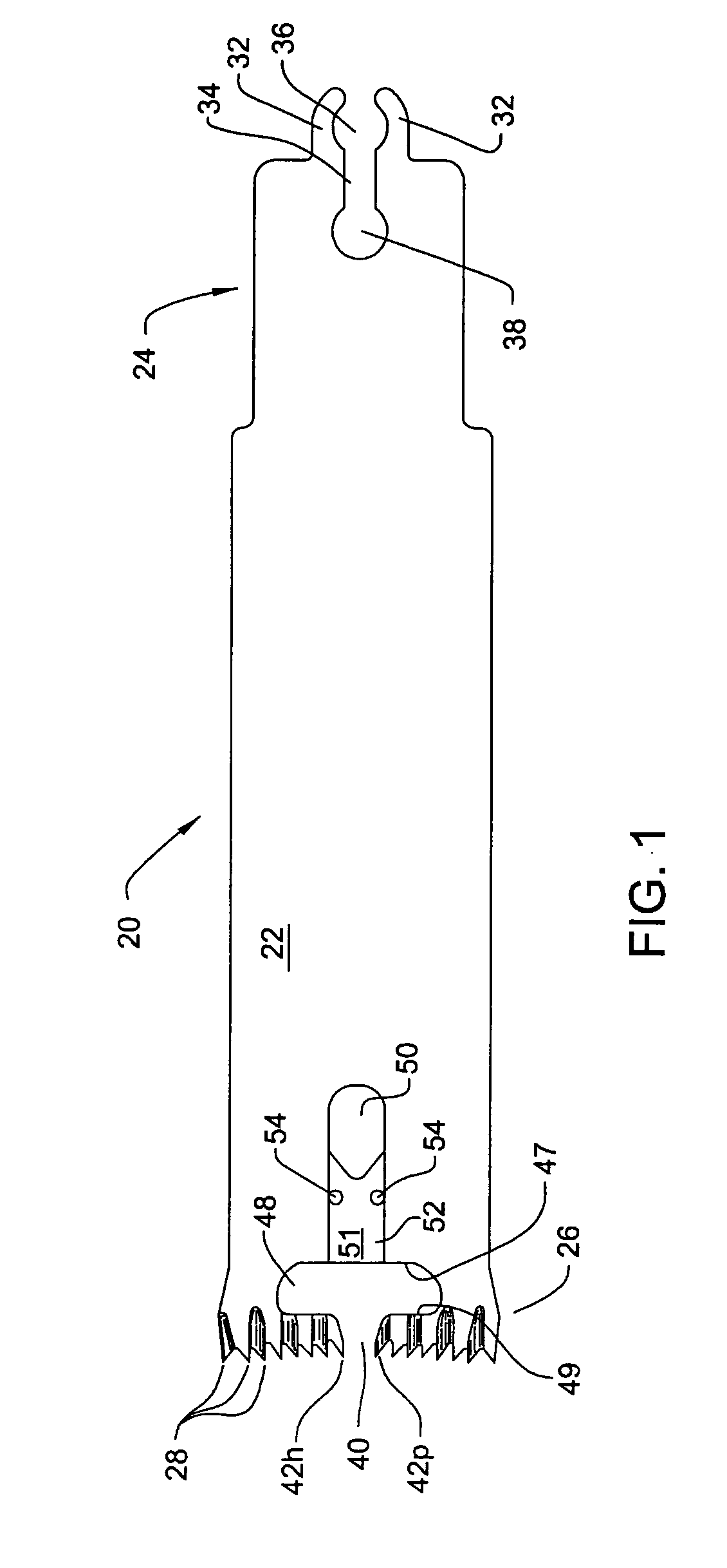
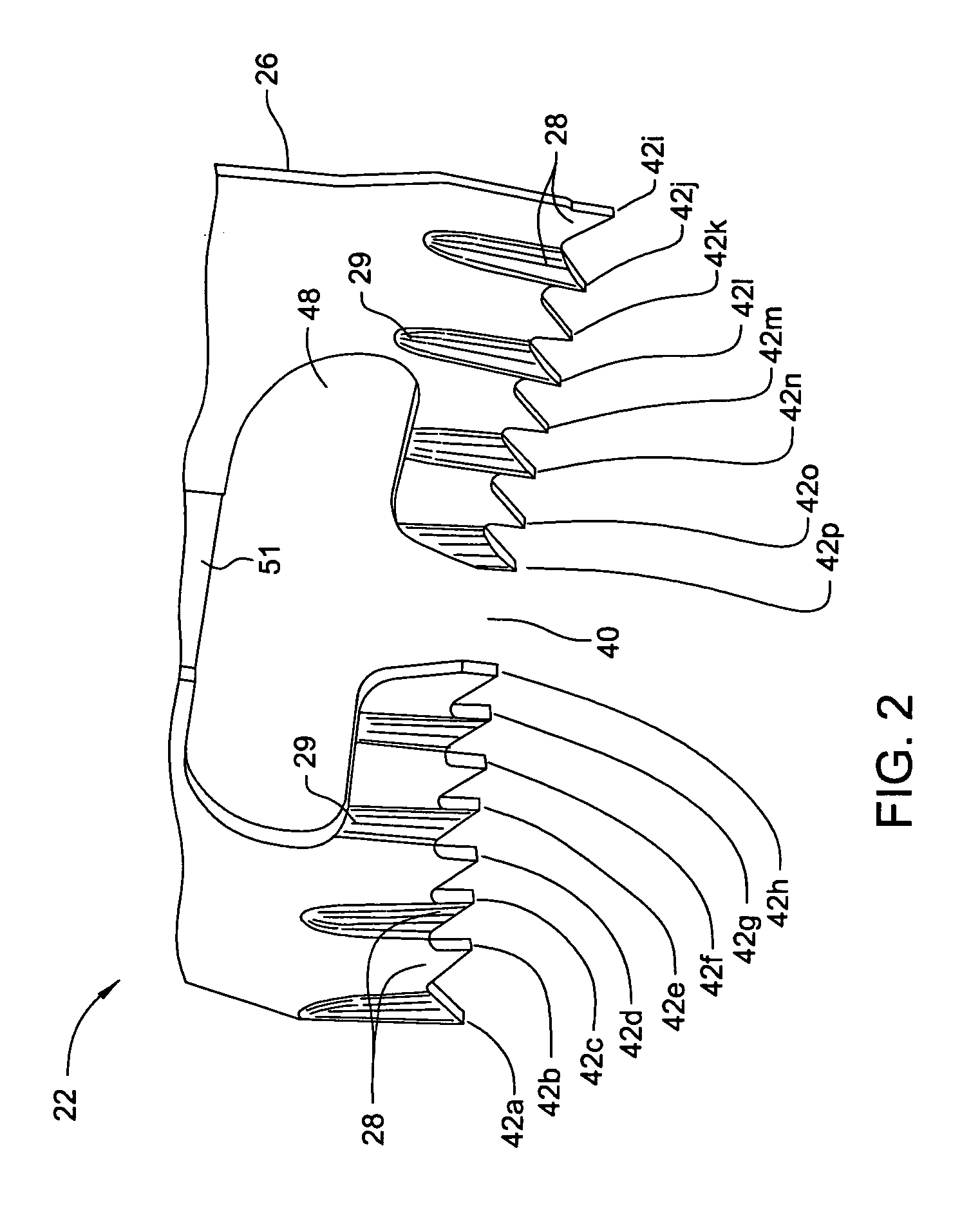
[0021]FIGS. 1 and 2 illustrate a surgical sagittal saw blade 20 constructed in accordance with this invention. Blade 20 has a planar blade body 22 formed of material such as stainless steel. Blade body 22 has opposed proximal and distal ends 24 and 26, respectively. (“Proximal” it is understood means towards the surgeon, away from the surgical site to which the blade is applied. “Distal” means away from the surgeon, towards the surgical site.) The blade is formed so that teeth 28 extend forward from the blade body distal end 26. Not identified are cuts formed in the distal end of the body 22 as a consequence of the machining of the teeth.

[0022] The blade 20 is further formed so that the body proximal end 24 is formed with geometric features that facilitate the coupling of the blade to the saw drive head that oscillates the blade. Specifically, saw blade 20 is a sagittal blade. Thus, the proximal end geometric features facilitate the coupling of the blade to a drive head that oscill...


PUM


Abstract

A sagittal saw blade wherein the teeth are arranged so that relative to the teeth located closer to the outer sides of the blade, the inner located teeth are located closer to the proximal end of the blade. The blade is further formed to have an opening between at least two of the teeth that extends proximally rearward. The opening increases in width as the opening extends proximally along the length of the blade. The opening opens into a void space that functions as a chip catchment space.

Description

RELATIONSHIP TO EARLIER FILED APPLICATION [0001] This application claims priority under 35 U.S.C. Sec. 119 from U.S. Patent Application No. 60 / 726,950 filed 15 Oct. 2005.FIELD OF THE INVENTION [0002] This invention relates generally to surgical saw blades. More particularly, this invention relates to a sagittal surgical saw blade that, when actuated, is relatively stable. This invention also relates to a surgical saw blade with a catchment for receiving bone chips formed by the blade. The invention also relates to a reciprocating surgical saw blade that efficiently cuts the tissue, bone, against which the blade is applied. BACKGROUND OF THE INVENTION [0003] In a surgical procedure, it is sometimes necessary to use a saw to remove tissue, including bone and cartilage. Often a powered saw is used to perform this procedure. Attached to the saw is a saw blade. A drive assembly internal to the saw reciprocates the blade in a back and forth motion. Some blades are constructed to pivot bac...

Claims


Application Information

Patent Timeline
Patent Type & Authority Applications(United States)
IPC IPC(8): A61B17/00
CPCA61B17/14A61B17/141A61B2019/462A61B17/148A61B2090/062A61B17/142A61B17/144
Inventor O' DONOGHUE, DENIS A.
Owner STRYKER EURO OPERATIONS HLDG LLC
Why Eureka
Try Eureka