Reflective light tube assembly for LED lighting

a technology of led lighting and light tube, which is applied in the direction of lighting and heating equipment, semiconductor devices for light sources, lighting support devices, etc., can solve the problems of short life expectancy, short life expectancy, and production of buzzing sound

Inactive Publication Date: 2012-01-17
BURRELL IV JAMES W
View PDF3 Cites 13 Cited by
  • Summary
  • Abstract
  • Description
  • Claims
  • Application Information

AI Technical Summary

Benefits of technology

[0008]The main object of the present invention is to provide a fluorescent tube replacement using efficient light emitting diode (LED) technology using a reflective LED light tube assembly wherein the light produced is not irritating to the eyes when looked at directly or indirectly and where the light produced is uniform.
[0009]It is another object of the present invention to provide a fluorescent tube replacement using efficient light emitting diode (LED) technology using a reflective LED light tube assembly that does not reduce the lumen output of the light emitting diodes.
[0012]It is a further object of the present invention to provide a fluorescent tube replacement using efficient light emitting diode (LED) technology using a reflective LED light tube assembly wherein the heat generated by the light emitting diodes is dissipated using a heat dissipating printing circuit board and thermoelectric cooling technology to reduce the operating temperature of the LEDs, increase the LEDs' functional lifetime, and to maintain the LEDs' high lumen output.
[0013]It is also an object of the present invention to provide a fluorescent tube replacement using efficient light emitting diode (LED) technology using a reflective LED light tube assembly wherein both parallel LED printed circuit boards are powered from only one end of the reflective LED light tube assembly (a slight cost reduction for manufacturing).
[0019]The power supply circuitry is disposed within one or both of the end caps, or can be located on the outside surfaces of both circuit boards, which can be cosmetically covered, but this will prevent heat dissipation.

Problems solved by technology

Fluorescent lighting produces uniform non-directional light and has advantages over incandescent lighting, but fluorescent light bulbs and ballasts have a short life expectancy, fail when subjected vibrations, consume high amounts of power, require a high operating voltage, may cause interference with sensitive electronics (electromagnetic interference (EMI) or radio frequency interference (RFI)), do not perform well in extreme cold environments, produce a buzzing sound, and are prone to flickering.
None of the prior art designs or solutions to improve the directional light output of fluorescent light tube retrofits using LED technology create an antiglare light output which is uniform and not irritating to the eyes.
Dispersing LED light directly at objects results in harsh and uneven lighting and the appearance of bright spots from the high lumen output of the LED and the narrow viewing angle of the LEDs.

Method used


Image

  • Reflective light tube assembly for LED lighting
  • Reflective light tube assembly for LED lighting
  • Reflective light tube assembly for LED lighting

Examples


first embodiment

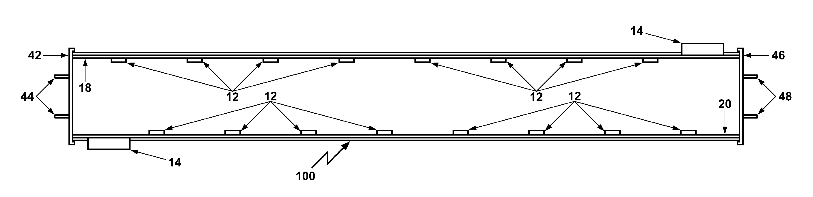
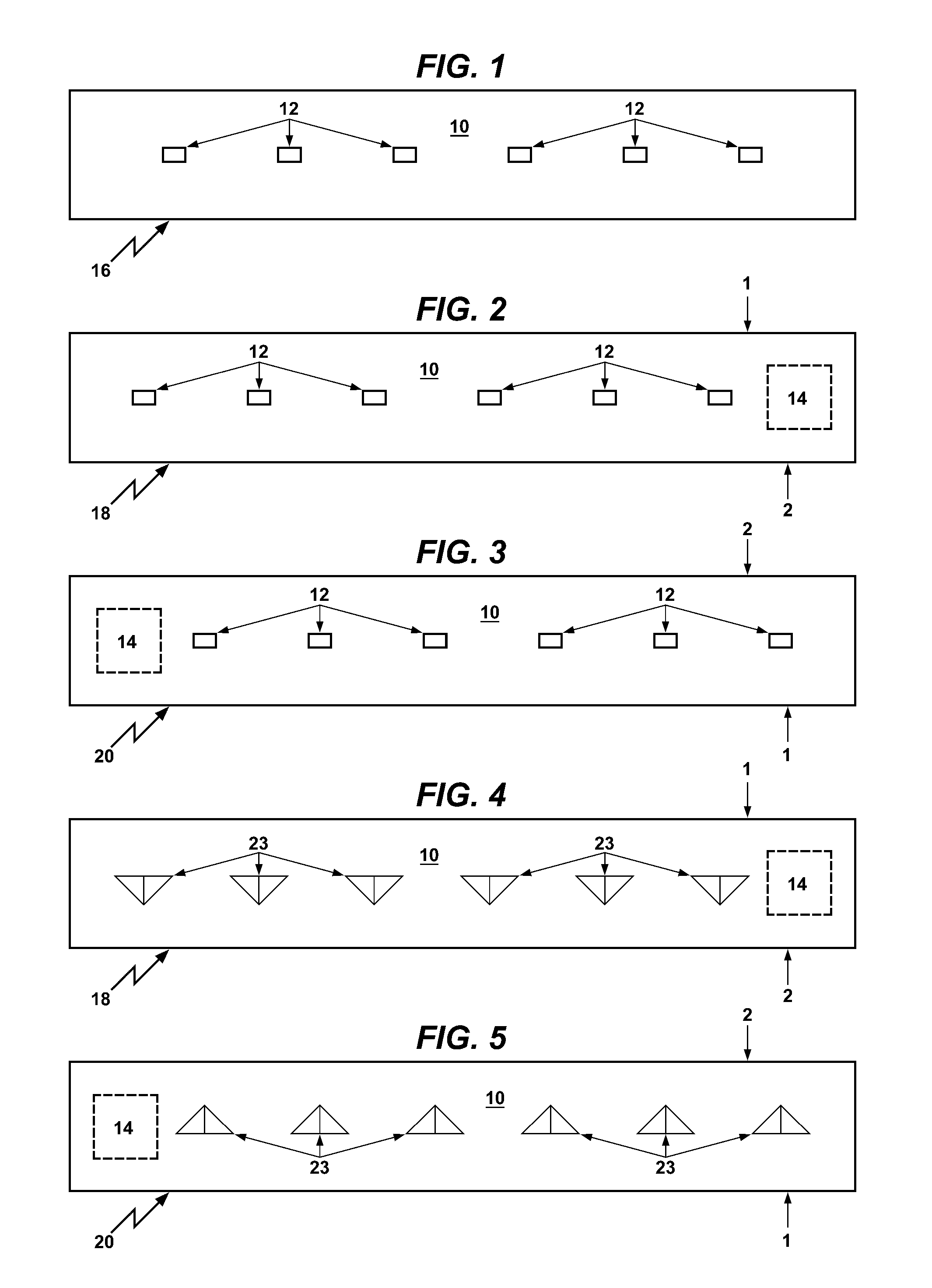
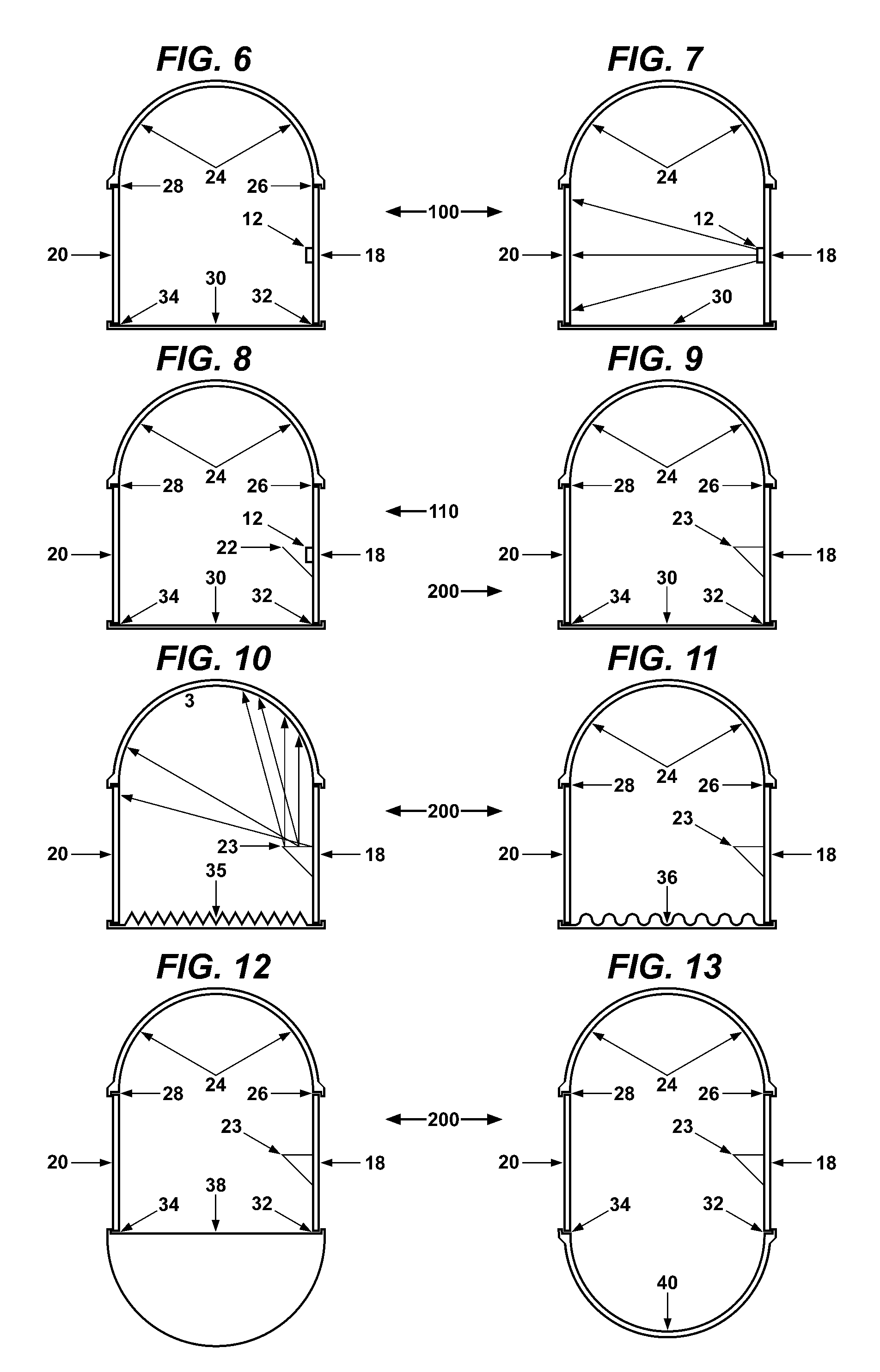
[0165]a first embodiment wherein the reflective heat dissipating LED PCBs 18 and 20 layers includes: 1) a thermoelectric cooling element 14 or layer 11 attached to the back of; 2) a heat dissipating LED PCB 10; and 3) a type of plastic or material layer (polished metal layer) with internal reflective surfaces (a dielectric spacer is used, if needed);

second embodiment

[0166]a second embodiment wherein the reflective heat dissipating LED PCBs 18 and 20 layers includes: 1) a thermoelectric cooling element 14 or layer 11 attached to the back of; 2) a heat dissipating LED PCB 10; with a 3) a dielectric material spacer 13 with thermal conductivity; externally attached to 4) a highly polished reflective side wall of an m-shaped metal chassis 68. The thermoelectric cooling element is not required in any preferred embodiment, but it increases efficiencies. A good dielectric material spacer 13 with thermal conductivity is the Bergquist S-Class Gap Pad® 5000S35, which has low thermal resistance and high thermal conductivity (5.0 W / m-K).

[0167]When an LED 12 is attached to a PCB, the LED 12 extends perpendicularly upwards are outwards from the PCB around 1 / 16 of an inch or more, making the assembly of the two preferred embodiments fast and easy. Although the present invention has been shown to use rectangular LEDs 12 vertically and horizontally aligned, the ...


PUM


Abstract

A reflective LED light tube assembly includes a bulb portion, a plurality of LEDs disposed inside the bulb portion on two longitudinal parallel facing heat dissipating reflective PCBs, both longitudinal PCB edges are longitudinally connected to a longitudinal reflective top portion and a longitudinal clear bottom portion, a pair of internally reflective end caps disposed at opposite ends of the bulb portion, a power supply circuit is disposed within one or both of the end caps or on the back of both PCBs, and a pair of male bi-pin electrical connectors extending from both end caps for electrical communication with the fluorescent light fixture's two tombstone female electrical connectors. One or both of the tombstone electrical connectors are in direct communication with an AC or DC power supply or circuit, which may also include a dimming feature. The LEDs illuminate in response to the electrical AC or DC current received in the power supply circuit.

Description

FIELD OF THE INVENTION[0001]The present invention relates to a reflective light emitting diode (LED) light tube assembly for reflectively dispersing the intense directional illumination of LEDs reflectively positioned inside the light tube assembly and for producing uniform linear light distribution, and more specifically, a reflective LED light tube assembly that can replace a fluorescent light bulb in a fluorescent light fixture, using solid-state electro-luminescence, powered by alternating current electricity and a preferred dimming feature.DESCRIPTION OF THE PRIOR ART[0002]Conventional fluorescent lighting systems include fluorescent light tubes and ballasts. Conventional fluorescent bulbs vaporize and ionize mercury gas (and argon, xenon, neon, or krypton gas at around 0.3% atmospheric pressure) using an electrical arc passing between two cathodes (preheat start-up, rapid start-up, or instant start-up electrodes) which produces ultraviolet rays that interact with the phosphor ...

Claims


Application Information

Patent Timeline
Patent Type & Authority Patents(United States)
IPC IPC(8): F21S4/00F21V21/00
CPCF21K9/17F21V19/0045F21Y2101/02F21Y2103/003Y10S362/80F21Y2103/10F21Y2115/10F21K9/60F21K9/68
Inventor BURRELL, IV, JAMES W.
Owner BURRELL IV JAMES W
Why Eureka
Try Eureka