Air shield for videoscope imagers

a videoscope and imager technology, applied in the field of imaging equipment, can solve the problems of inaccurate image capture, turbulence of liquid, inaccurate and distorted images, etc., and achieve the effect of substantially reducing or eliminating the cleaning of the imag

Active Publication Date: 2012-01-17
HARREL STEPHEN K
View PDF25 Cites 59 Cited by
  • Summary
  • Abstract
  • Description
  • Claims
  • Application Information

AI Technical Summary

Benefits of technology

[0010]In accordance with the principles and concepts of the invention, there is disclosed a videoscope with an imager having an optical input embedded within the envelope of an air stream to thereby deflect particles directed toward the lens. An object of the invention is to prevent debris from contaminating the optical input of the imager so that cleaning thereof is either substantially reduced or eliminated.

Problems solved by technology

By manipulating the end of the videoscope in or around the patient's tissue, the doctor can view the procedure on the video display, which might otherwise be very difficult or impossible for the doctor to see with the naked eye or head-mounted optical magnifying equipment.
A problem often encountered with the use of an imaging type of endoscope or a videoscope is that of maintaining the lens or optical input of the imager clean during the procedure.
The flushing of the area often causes the debris to be splattered onto the lens of the imager, thus requiring the same to be removed and cleaned, or withdrawn somewhat during the lavage procedure.
It can also be appreciated that even when water or another clear liquid is used to keep the lens clean, the cleaning liquid can often leave droplets on the lens, thereby creating inaccurate capturing of the image.
In addition, in cases where the imager is immersed within the liquid during the operation, the motion and turbulence of the liquid produces inaccurate and distorted images.
When a conventional video imager is used, whether it be a miniature camera or the end of a fiber optic bundle, the optical input quickly becomes contaminated with blood and must be repeatedly cleaned.
If a rotary or ultrasonic instrument is used, of the type that produces copious spray and blood-contaminated aerosols, the image captured becomes virtually unusable.
The end of the videoscope nevertheless becomes contaminated and must be frequently removed and cleaned.
These videoscopes are believed to function well for their intended purpose, but the excess liquid must be evacuated from the surgical site, or it will also obscure and interfere with the line of sight to the area of interest.
The videoscopes described in the prior art facilitate the removal of splatter once it accumulates on the lens of the imager by flooding the area adjacent the lens with water, but do not address prevention of the same.

Method used


Image

  • Air shield for videoscope imagers
  • Air shield for videoscope imagers
  • Air shield for videoscope imagers

Examples


Embodiment Construction

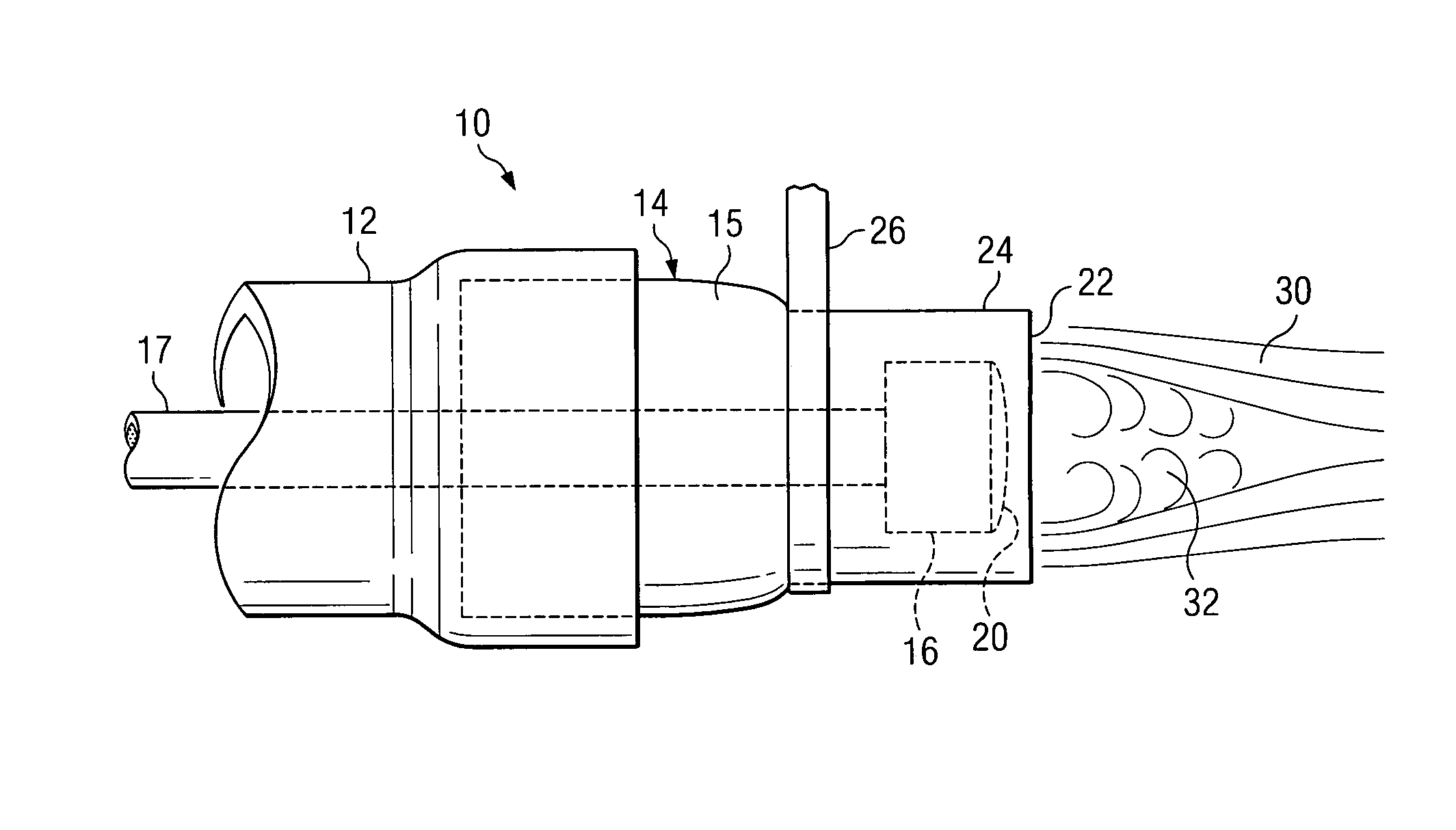
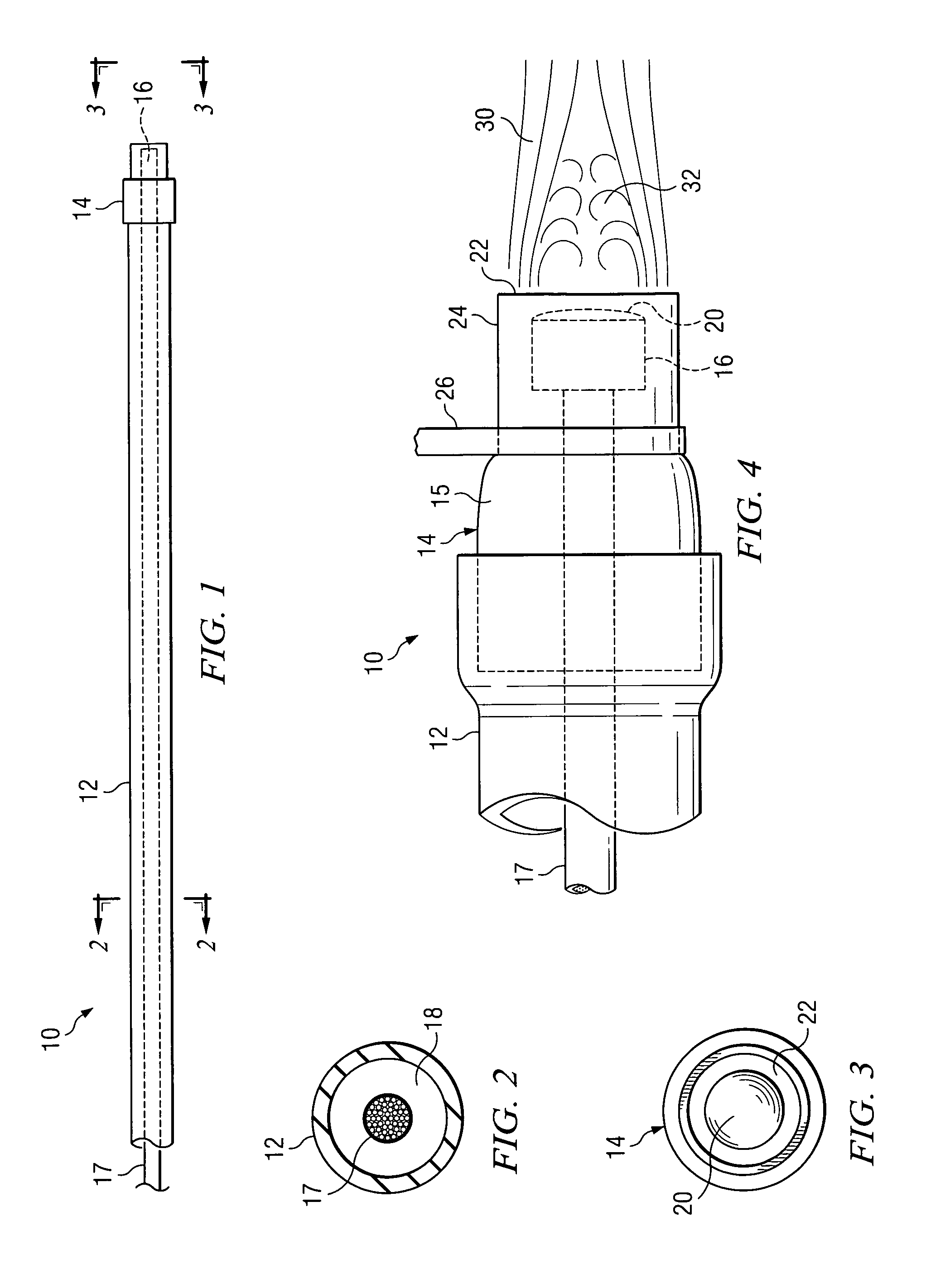
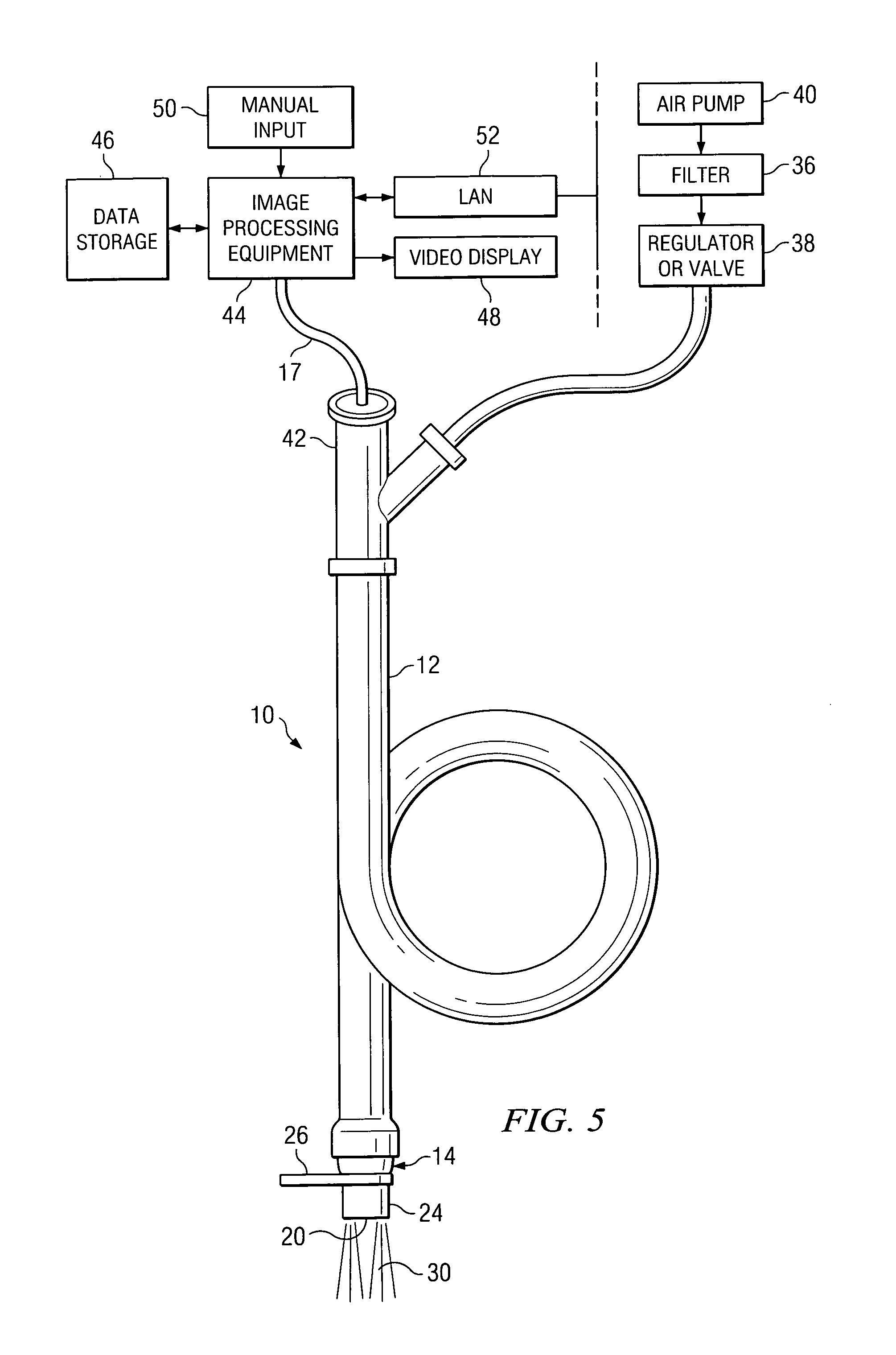
[0030]With reference to FIG. 1, there is shown the air shield 10 according to one embodiment of the invention. The air shield 10 includes a flexible plastic, rubber or silicon tube 12 having a termination fitting 14 comprising a tubular metal member fixed to the end of the tube 12. While not shown, the other end of the tubing 12 is connected to a source of pressurized gas, such as air, nitrogen or other suitable gas medium. Inserted within the tubing 12 is a miniature camera 16 with a lens comprising the image input of the imager. In the preferred embodiment of the invention, the miniature camera 16 has a 3.5 megapixel semiconductor imager, is self focusing, has a diameter of about 2.8 mm, and is obtainable from Olympus as model number ENF-V2. The miniature camera 16 couples digital signals representative of the image captured, through an electrical cable 17 to remotely located image processing equipment. The camera 16 includes a lens (not shown) which is positioned near the end of ...


PUM


Abstract

An air shield for a videoscope imager to prevent obscuring of the optical input by body liquids and tissue particles. The imager is extended through a tube carrying a pressurized gas so that when the gas escapes from the end of the tube, it generates an air stream envelope around the optical input of the imager and prevents liquids and particles directed toward the optical input from contacting the optical input. The pressurized gas flows continuously during the medical or dental procedure to maintain a constant resistance to liquids and matter directed to the optical input of the imager.

Description

TECHNICAL FIELD OF THE INVENTION[0001]The present invention relates in general to imaging apparatus for use with endoscopic and videoscope equipment, and in particular relates to methods and apparatus for maintaining imaging lenses clean during minimally invasive surgical procedures.BACKGROUND OF THE INVENTION[0002]Significant advances have been made in the medical and dental fields to better enable doctors to view and observe the treatment area during surgical procedures in the medical and dental field. Where previously a doctor used a head-mounted magnifying eyepiece to view the tissue area, now doctors routinely use electronic imaging apparatus to display an enlargement of the tissue area so that the area can be viewed on a screen with selected angles, intensities, colors, and so that a number of persons can simultaneously view the same tissue area of interest. Moreover, with electronic imaging, the images can be magnified for viewing, stored for archive purposes, and can be view...

Claims


Application Information

Patent Timeline
Patent Type & Authority Patents(United States)
IPC IPC(8): A61B1/12
CPCA61B1/00135A61B1/0014A61B1/015A61B1/05A61B1/123A61B1/24
Inventor HARREL, STEPHEN K.
Owner HARREL STEPHEN K
Why Eureka
Try Eureka