Heat exchanger and method for use in precision cooling systems

a technology of heat exchanger and cooling system, which is applied in the direction of indirect heat exchanger, lighting and heating apparatus, and stationary conduit assemblies, etc., can solve the problems of reducing the performance level of newer, more powerful, and less efficient heat generation of high-heat-producing systems

Active Publication Date: 2012-02-21
VERTIV CORP
View PDF31 Cites 34 Cited by
  • Summary
  • Abstract
  • Description
  • Claims
  • Application Information

AI Technical Summary

Problems solved by technology

Due to the demand for more components in increasingly smaller spaces, computer and electronic systems are increasingly configured and designed to be closer together, and many existing cooling systems for these electronic systems may not provide adequate heat removal.
Thus, these new components are driving up the heat production of new computer and electronic designs to the point where traditional heat cooling methods may not provide enough cooling capacity to these new systems to operate at their designed conditions in close-packed, enclosed spaces, such as rack enclosures.
As a result, these newer, more powerful, high heat-producing systems may have to operate at reduced performance levels to limit the heat generation.
Further, some locations in a computer cabinet, rack or other electronic system may be hotter than others during operation of the system because there may be a density of components and / or poor positioning with respect to the flow of cooling air.
Consequently, some components may not be adequately cooled.
Also, these types of systems usually dumped the removed heat load into the general environment, such as a computer room, which may overload the environmental cooling system.
A higher refrigerant evaporation temperature in the heat exchanger may lead to a decrease in the overall cooling capacity of heat exchanger because the temperature difference between the heated air and refrigerant evaporation temperature decreases, and the system is not able to remove as much heat from the air.
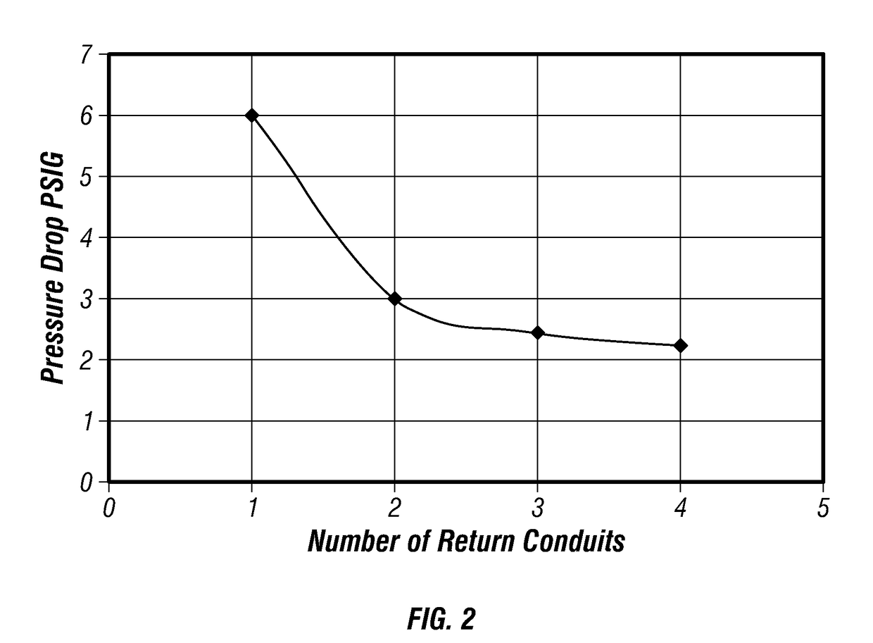
In addition, increased flow rate of fluid through a heat exchanger tends to increase the pressure drop across the heat exchanger.

Method used


Image

  • Heat exchanger and method for use in precision cooling systems
  • Heat exchanger and method for use in precision cooling systems
  • Heat exchanger and method for use in precision cooling systems

Examples


Embodiment Construction

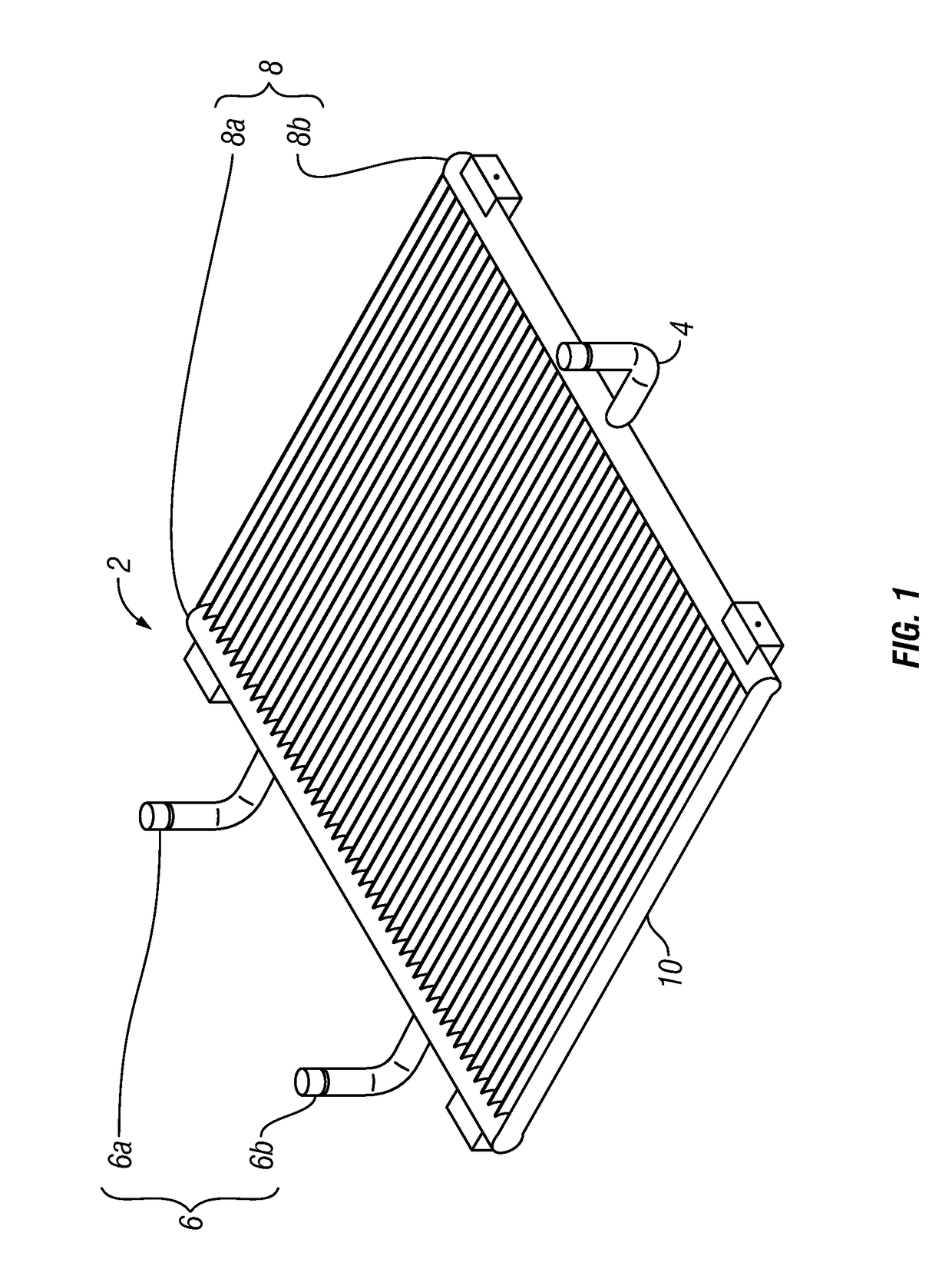
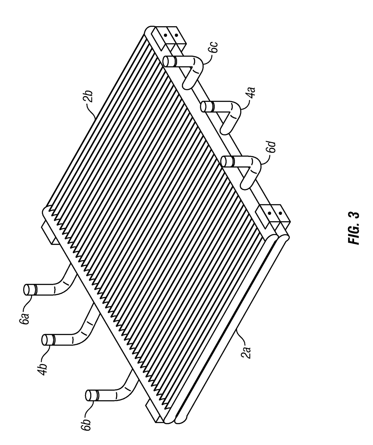
[0023]The Figures described herein and the written description of specific structures and functions below are not presented to limit the scope of the invention disclosed and taught herein or the scope of the appended claims. Rather, the Figures and written description are provided to teach any person skilled in the art to make and use the inventions for which patent protection is sought. Those skilled in the art will appreciate that not all features of a commercial embodiment of the inventions are described or shown for the sake of clarity and understanding. Persons of skill in this art will also appreciate that the development of an actual commercial embodiment incorporating aspects of the present inventions will require numerous implementation-specific decisions to achieve the developer's ultimate goal for the commercial embodiment. Such implementation-specific decisions may include, and likely are not limited to, compliance with system-related, business-related, government-relate...


PUM


Abstract

An improved precision cooling system for high heat density applications comprises a heat exchanger having more fluid outlet conduits than fluid inlet conduits to optimize the pressure drop across the heat exchanger at a given fluid flow rate. The heat exchanger may be of microchannel or tube fin construction, and the cooling system may utilize single phase or multi-phase pumped or compressed fluids.

Description

CROSS REFERENCE TO RELATED APPLICATIONS[0001]Not applicable.STATEMENT REGARDING FEDERALLY SPONSORED RESEARCH OR DEVELOPMENT[0002]Not applicable.REFERENCE TO APPENDIX[0003]Not applicable.BACKGROUND OF THE INVENTION[0004]1. Field of the Invention[0005]The inventions disclosed and taught herein relate generally to a precision cooling systems for heat generating objects; and more specifically to an improved heat exchanger for use in precision cooling systems for high density heat load environments.[0006]2. Description of the Related Art[0007]Many new computer and electronic system designs combine multiple heat-producing components, such as microprocessors or processor boards, in an enclosed environment. Supercomputers and other large computer systems typically include a large number of processors housed in cabinets or racks. Due to the demand for more components in increasingly smaller spaces, computer and electronic systems are increasingly configured and designed to be closer together...

Claims


Application Information

Patent Timeline
Patent Type & Authority Patents(United States)
IPC IPC(8): F28F7/00
CPCF28D1/0417F28D1/05383F28F9/026F28D2021/0064F28F2260/02
Inventor HARVEY, THOMAS E.
Owner VERTIV CORP
Why Eureka
Try Eureka