Bicycle damper

US20090277732A1Active Publication Date: 2009-11-12SPECIALIZED BICYCLE COMPONENTS INC

Image

  • Bicycle damper
  • Bicycle damper
  • Bicycle damper

Examples


Embodiment Construction

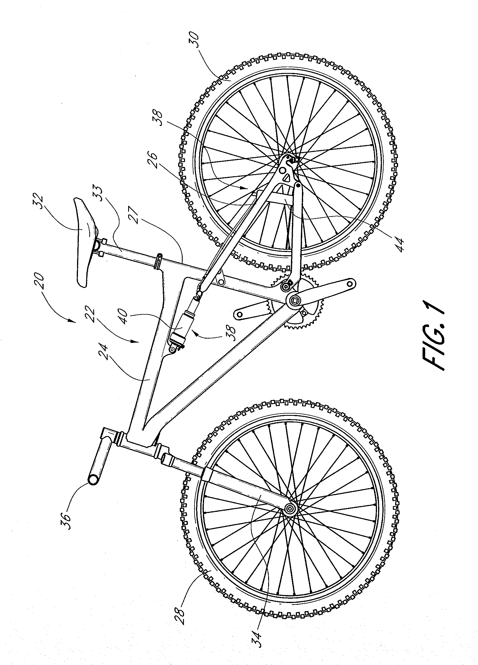
[0037]Referring to FIG. 1, a bicycle 20 (e.g., a mountain bike) having a preferred embodiment of a rear suspension assembly including a rear suspension element, or shock absorber, is illustrated. The bicycle 20 includes a frame 22, preferably comprised of a generally triangular main frame portion 24 and an articulating frame portion, or subframe 26, which preferably is pivotally connected to the main frame portion 24. In the illustrated arrangement, the subframe 26 is an assembly of multiple linkage members pivotally connected to one another. The subframe 26 is pivotally connected to the main frame portion 24 (e.g., to the seat tube 27). The bicycle 20 also includes a front wheel 28 and a rear wheel 30. The rear wheel 30 is carried by the subframe 26. A saddle or seat 32, to provide support to a rider in a sitting position, is connected to the main frame 24 and, in particular, to the seat tube 27. In the illustrated arrangement, the seat 32 is connected to the main frame 24 through ...


PUM


Abstract

A damper for a bicycle having, in one arrangement, a primary unit and a remote unit. The primary unit includes a damper tube, a spring chamber, and a piston rod that supports a main piston. The main piston is movable within the damper chamber of the primary unit. The main piston and the damper tube at least partially define a compression chamber. The remote unit comprises a remote fluid chamber and an inertial valve within the remote unit. The inertial valve is preferably responsive to terrain-induced forces and preferably not responsive to rider-induced forces when the shock absorber is assembled to the bicycle. A fluid flow control arrangement within the remote unit utilizes compression fluid flow to delay closing of the inertia valve after acceleration forces acting on the inertia valve diminish. In some arrangements, the inertia valve and fluid flow control arrangement may reside in the primary unit.

Description

INCORPORATION BY REFERENCE[0001]The entireties of U.S. patent application Ser. No. 12 / 197,171, filed Aug. 22, 2008, and U.S. Provisional Patent Application No. 61 / 054,091, filed May 16, 2008, and 61 / 051,894, filed May 9, 2008, are hereby incorporated by reference herein and made a part of the present specification.BACKGROUND OF THE INVENTION[0002]1. Field of the Invention[0003]The present invention generally relates to vehicle suspension systems including acceleration-sensitive damping. More specifically, the present invention relates to a shock absorber with a fluid flow control arrangement for an acceleration-sensitive damping circuit to be incorporated into the suspension system of a bicycle.[0004]2. Description of the Related Art[0005]Bicycles intended for off-road use, i.e., mountain bikes, commonly include a suspension assembly operably positioned between the rear wheel of the bicycle and the frame of the bicycle. The suspension assembly typically includes a shock absorber con...

Claims


Application Information

Patent Timeline
12 Nov 2009
Publication
US20090277732A1
IPC
F16F9/34
CPC
F16F9/504
Inventors
TRUJILLO, ANTHONY; MCANDREWS, MICHAEL