Air infeed device for air-conditioning passenger areas in aircraft

Inactive Publication Date: 2012-02-21
DIEHL AIRCABIN
View PDF13 Cites 11 Cited by
  • Summary
  • Abstract
  • Description
  • Claims
  • Application Information

AI Technical Summary

Benefits of technology

[0016]Provision may also be made for each depression to have an essentially triangular shape, a base side of the triangle extending in the same direction as the slit-shaped aperture and a point of said triangle pointing in the direction of an air inlet pipe. In conjunction with the abovementioned design features of the central air infeed module, a depression constructed in the base member of said central air infeed module guarantees improved air distribution within the latter. It serves, in particular, as a guide face for the air flowing through said module and ensures that an air flow that flows out in a uniform manner is guaranteed, not only in a central region of the air outlet aperture but also in its edge regions.
[0017]Another form of embodiment of the invention makes provision for the base member of the central air infeed module to have, on the convex rear side, a depression, which extends in the direction of the longitudinal axis of the air infeed device, for receiving the corresponding individual air infeed module. Since said individual air infeed module is then partially received in the central air infeed

Problems solved by technology

Furthermore, preassembly of the components reduces the number of fitting steps

Method used


Image

  • Air infeed device for air-conditioning passenger areas in aircraft
  • Air infeed device for air-conditioning passenger areas in aircraft
  • Air infeed device for air-conditioning passenger areas in aircraft

Examples


Example

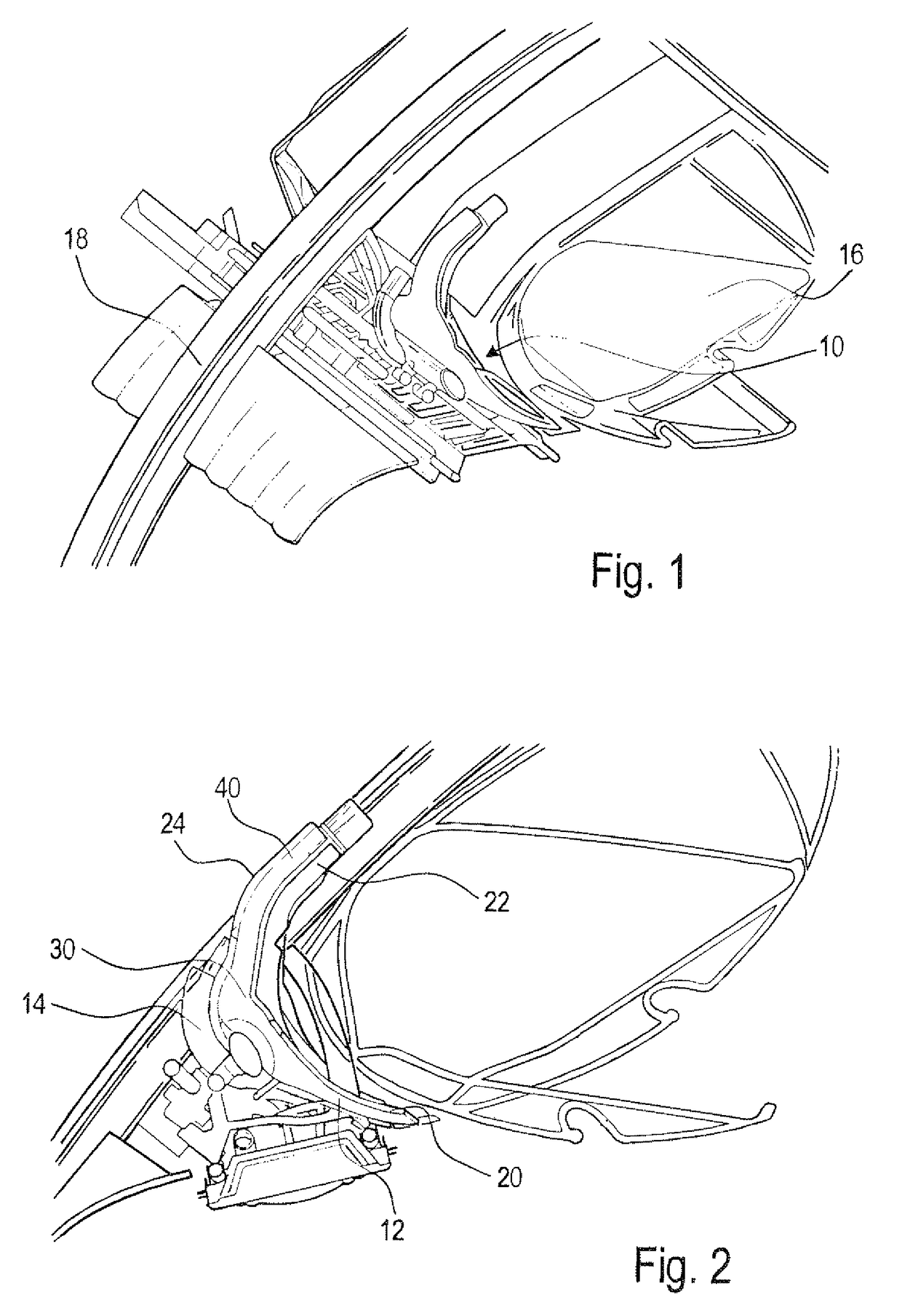
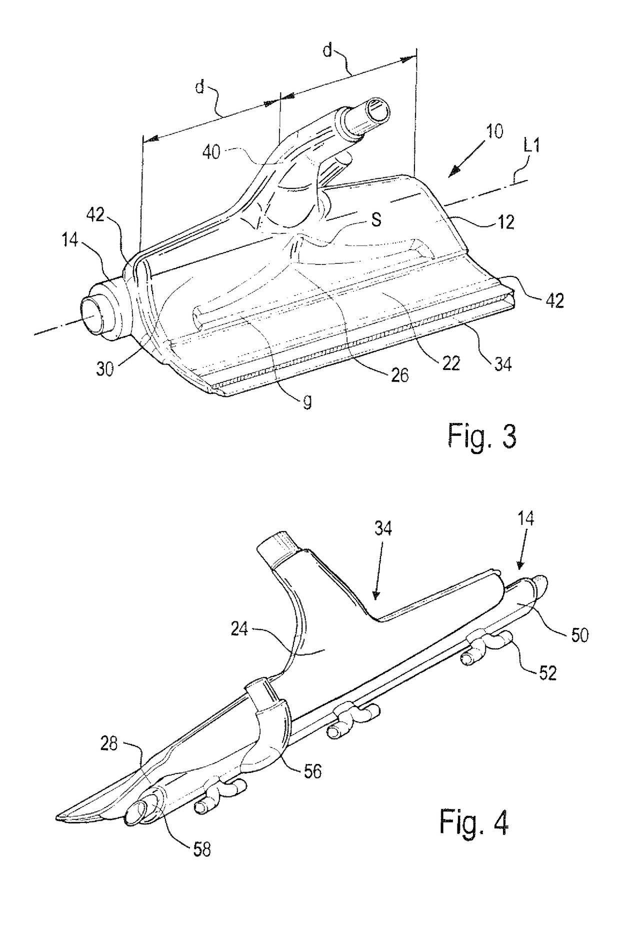
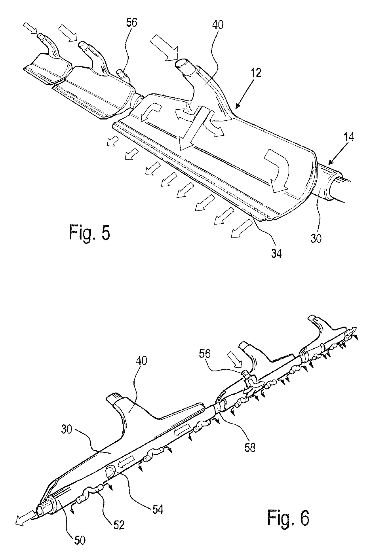
[0031]An air infeed device 10 according to the invention can be seen in the installed condition in FIGS. 1 and 2. A luggage locker 16 is located above said air infeed device 10, the rearward termination being formed by a rib 18. As can also be seen with the aid of FIGS. 3 to 6, said air infeed device 10 has a central air infeed module 12 for the centrally regulated cabin ventilation, and an individual air infeed module 14 for the individually adjustable ventilation. As previously described, the central air infeed module 12 and the individual air infeed module 14 are fluidically uncoupled (i.e., the respective duct systems are separate from one another). In that form of embodiment of the air infeed device 10 according to the invention which is shown, the individual air infeed module 14 is received in a depression 28 which is located on the convex rear side 24 of the central air infeed module 12.

[0032]It clearly emerges from FIGS. 1 and 2 that, viewed in the direction of a longitudina...


PUM


Abstract

An air infeed device for air-conditioning passenger areas in aircraft includes a central air infeed module for the centrally regulated cabin ventilation system and an individual air infeed module for the individually adjustable cabin ventilation system. The centrally regulated cabin ventilation system and the individually adjustable cabin ventilation system are mutually independent systems. The central air infeed module and the individual air infeed module are connected to form a subassembly that can be handled independently as a collective unit.

Description

TECHNICAL FIELD[0001]The invention relates to an air infeed device for air-conditioning passenger areas in aircraft. This device has a central air infeed module for the centrally regulated cabin ventilation and an individual air infeed module for the ventilation which can be adjusted individually by the passenger. It also relates to an air infeed installation having an air infeed device of this kind.BACKGROUND[0002]As a rule, commercial aircraft have an air infeed installation with two mutually independent air infeed systems for air-conditioning the passenger cabin. A central air infeed system which is regulated centrally, for example via the cockpit, serves, above all, for that continuous infeed of fresh air which is necessary because of the large passenger density in an aircraft cabin. Air outlet apertures belonging to the central air infeed system may be disposed both in the foot area of the aircraft's passenger cabin and also in the region of the stowage lockers for luggage whic...

Claims


Application Information

Patent Timeline
IPC IPC(8): B64D13/00
CPCB64D13/00B64D2013/0625
Inventor BRUGGEN, LARSKOBLER, MATTHIASSTUTZER, JORG
Owner DIEHL AIRCABIN
Why Eureka
Try Eureka